Data, Termination board installation, Termination – ETC Desire Series XTI v1.6.0 User Manual
Page 23
1
Installation and DMX Profiles
18
Data
The D40/D60 XTI fixture operates on a DMX control signal or as a standalone fixture. The
fixture is supplied with cable that includes DMX input and thru. DMX cables should be
acceptable for DMX data transmission (not microphone cable) and should follow the
standard pinout. The optional secondary data pair is not used by the D40/D60 XTI fixtures.
The maximum DMX data run from any DMX source to the last fixture in a chain is 1000 feet
(300m).
Use Belden
®
9729, CAT-5e, or equivalent Shielded Twisted Pair (STP) or Unshielded
Twisted Pair (UTP) cable to connect the D40/D60 XTI into an IDC (Insulation Displacement
Connector) style connector.
See
for information on DMX addressing of D40/D60 XTI fixtures.
Termination Board Installation
Each D40/D60 XTI fixture is connected to the network through a Termination board which
is installed in a junction box that is suitable for outdoor use. The DMX cable from the fixture
is connected to the Termination board.
Termination
The Desire D40/D60 XTI Series requires that the last fixture on a DMX/RDM line be
terminated with a 120 ohm resistor, which is accomplished with the S1 switch on the
Termination board. Set the switch to the ON position to terminate the last fixture. All others
on the DMX/RDM line must be set to OFF.
Cat 5e: DMX 512 Pinout
Belden 9729: DMX 512
1
Common Shield
1
Common Shield
2
Data -
2
Data -
3
Data +
3
Data +
4
Unused Conductor
4
Not Connected
5
Unused Conductor
5
Not Connected
6
Unused Conductor
6
Not Connected
7
Unused Conductor
7
Not Connected
8
Unused Conductor
8
Not Connected
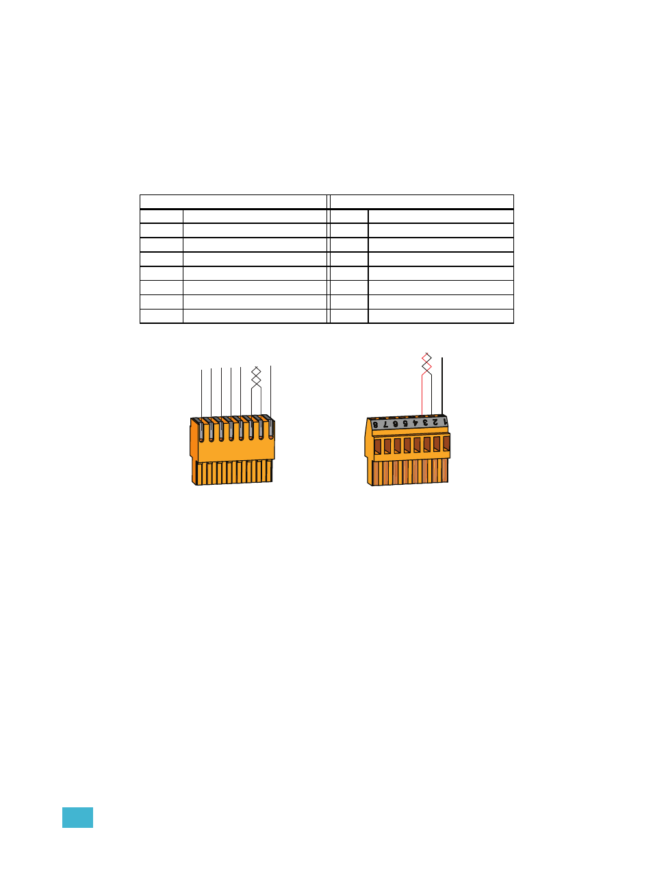
Data – (ORG)
Data + (W/ORG)
Cat5 (or equivalent) wire
termination to IDC connector
COM
BRN
GRN
W/GRN
BLU
W/BLU
From a DMX/RDM source
Data – (Black)
Data + (Red)
Belden 9729 (or equivalent) wire
termination to screw connector
4 to 8 = n/c
COM