Communication cables, Rs-232 communication – ElmoMC ExtrIQ Digital Servo Drives-Eagle User Manual
Page 60
Eagle Installation Guide
Installation
MAN-EAGIG (Ver. 1.902)
60
3.4.8.
Communication Cables
The communication cables use a 9-pin D-Sub plug that connect to the RS-232 and 9-pin D-Sub
socket that connects to the CAN ports on the Eagle. The communication interface may differ
according to the user’s hardware. The Eagle can communicate using the following options:
a.
RS-232, full duplex
b.
CAN
RS-232 communication requires a standard, commercial 3-core null-modem cable connected from
the Eagle to a serial interface on the PC. The interface is selected and set up in the Composer
software.
In order to benefit from CAN communication, the user must have an understanding of the basic
programming and timing issues of a CAN network. The interface is electrically isolated by
optocouplers. For ease of setup and diagnostics of CAN communication, RS-232 and CAN may be
used simultaneously.
3.4.8.1.
RS-232 Communication
Notes for connecting the RS-232 communication cable:
•
Use a 24, 26 or 28 AWG twisted pair shielded cable (24 AWG cable is recommended). The
shield should have aluminum foil covered by copper braid with a drain wire.
•
Connect the shield to the ground of the host (PC). Usually, this connection is soldered
internally inside the connector at the PC end. You can use the drain wire to facilitate
connection.
•
Use only a D-Sub connector with a metal housing.
•
Attach the braided shield tightly to the metal housing of the D-type connector.
•
When assembling the Communication cable, follow the instructions in Section 3.4.3 (Feedback
Control and Communication Cable Assemblies).
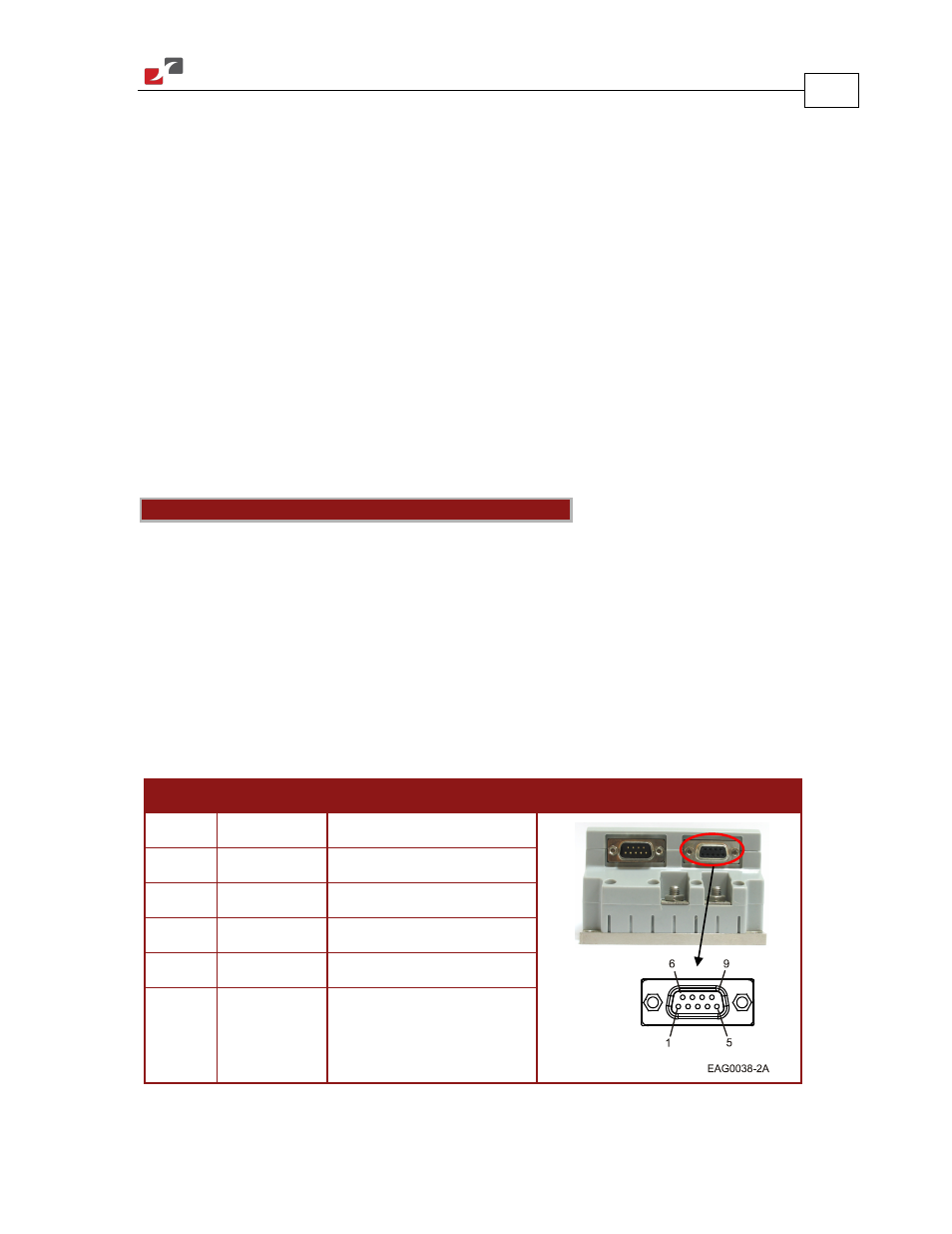
Pin
Signal
Function
Pin Locations
1
—
—
2
Tx
RS-232 transmit
3
Rx
RS-232 receive
4
—
—
5
COMRET
Communication return
6, 7, 8
—
—
Table 15: RS-232 Cable – Pin Assignments
J2
Female