ElmoMC ExtrIQ Digital Servo Drives-Eagle User Manual
Page 34
Eagle Installation Guide
Installation
MAN-EAGIG (Ver. 1.902)
34
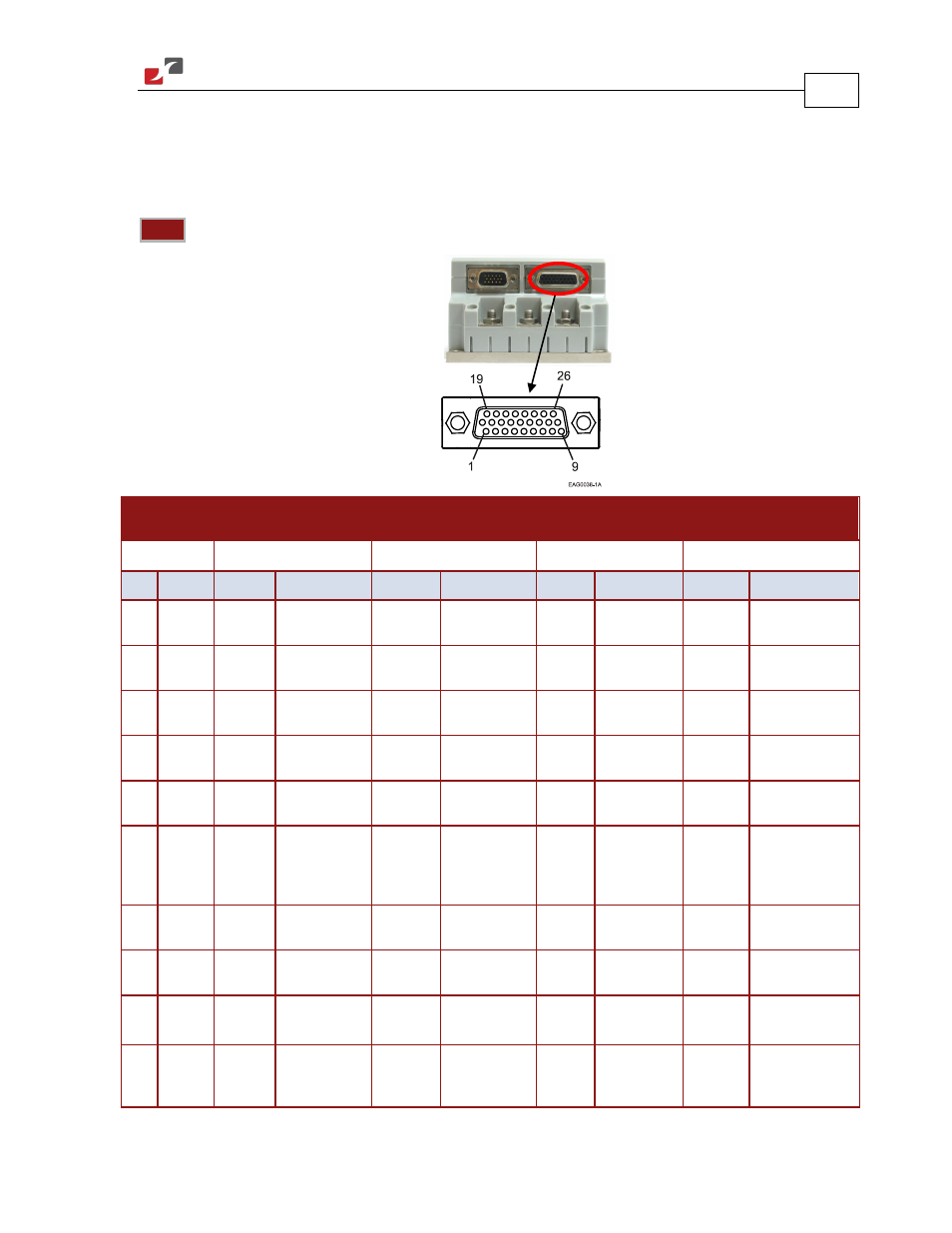
Feedback A on the “front” of the Eagle has a 26-pin high density D-Sub socket. Connect the Main
Feedback cable from the motor to Feedback A using a 26-pin, high density D-Sub plug with a metal
housing. When assembling the Main Feedback cable, follow the instructions in Section 3.4.3
(Feedback Control and Communication Cable Assemblies).
Note:
The Feedback connector also supports Feedbacks A and B.
Incremental
Encoder
Interpolated
Analog Encoder
Resolver
Tachometer and
Potentiometer
EAG-
XX
/
YYY
_
EAG-
XX
/
YYY
I
EAG-
XX
/
YYY
R
EAG-
XX
/
YYY
T
Pin Port
Signal Function
Signal
Function
Signal Function
Signal Function
1 A– Main
Input
CHA
Channel A
A+
Sine A
S1
Sine A
Tac1+
Tacho Input 1 Pos.
(20 V max)
2 A– Main
Input
CHA-
Channel A
Complement
A-
Sine A
Complement
S3
Sine A
Complement
Tac1-
Tacho Input 1 Neg.
(20 V max)
3 A– Main
Input
CHB
Channel B
B+
Cosine B
S2
Cosine B
Tac2+
Tacho Input 2 Pos.
(50 V max)
4 A– Main
Input
CHB-
Channel B
Complement
B-
Cosine B
Complement
S4
Cosine B
Complement
Tac2-
Tacho Input 2 Neg.
(50 V max)
5 A– Main
Input
INDEX
Index
R+
Reference
R1
Vref f=1/TS,
50 mA Max.
POT
Potentiometer
Input
6 A– Main
Input
INDEX-
Index
Complement
R-
Reference
Complement
R2
Vref
complement
f = 1/TS,
50 mA Max.
NC
-
7 Hall A
HA
Hall sensor A
input
HA
Hall sensor A
input
HA
Hall sensor A
input
HA
Hall sensor A input
8 Hall B
HB
Hall sensor B
input
HB
Hall sensor B
input
HB
Hall sensor B
input
HB
Hall sensor B input
9 Hall C
HC
Hall sensor C
input
HC
Hall sensor C
input
HC
Hall sensor C
input
HC
Hall sensor C input
10 B2 – Aux.
Output
CHAO
Aux./Main
channel A high
output
CHAO
Aux./ Emulated
channel A high
output
CHAO
Aux./
Emulated
channel A high
CHAO
Aux./ Emulated
channel A high
output
J4 Female