ElmoMC SimplIQ Digital Servo Drives-Bell Getting Started User Manual
Page 74
The SimplIQ for Steppers Getting Started & Tuning and Commissioning Guide
MAN-BELGS (Ver. 1.1)
74
If a settling time of 25 msec at least is satisfactory, try to insert a second order
low-pass filter. The starting corner frequency is (10/Settling time) Hz. Iterate step
2 for low-pass filters decreasing by 25% each test. Repeat, decreasing the low-
pass frequency until a satisfactory controller is achieved; see Guideline 4 below.
Guideline 4: A satisfactory result is the low-pass filter with the lowest corner
frequency that satisfies the required performance. The low-pass minimizes the
expected current consumption and current noise level.
A.8.3 Manual Tuning of a PI Controller and a Notch Filter
During the design of a PI controller, the designer can conclude from the test
results if a notch filter is required and in which frequency it should be added.
Below is a characteristic example, using the second (resonant) test system.
Let us start designing a PI controller. After several iterations increasing KI and
KP (KI/KP=
2
π
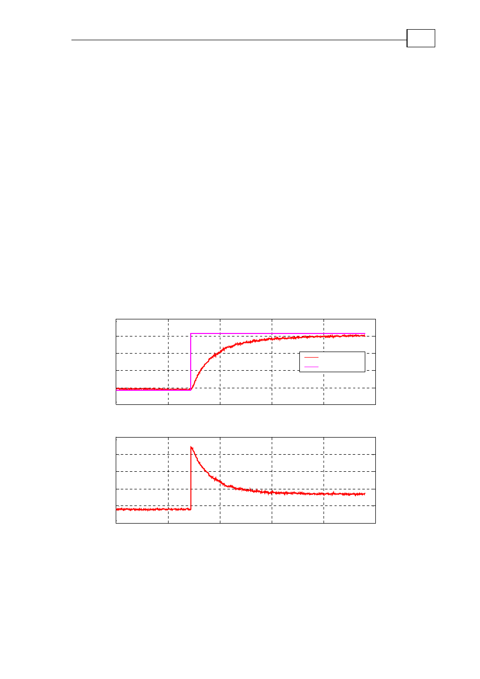
), we have the test results given in Figure 67. The measured
current exhibits oscillations, which indicates the existence of resonance.
Remark: In this example the measured speed also exhibits oscillations. In most
cases, however, the resonance phenomenon is more clearly identified from the
current response than from the speed response.
0
0.1
0.2
0.3
0.4
0.5
-3
-1.8
-0.6
0.6
1.8
3
x 10
4
Tim e (sec.)
C
ount
s
/s
e
c
.
Speed
Reference
0
0.1
0.2
0.3
0.4
0.5
-0.8
-0.16
0.48
1.12
1.76
2.4
Am
p
e
re
Tim e (sec.)
Figure 67: Example of a test, which calls for using a notch – the current exhibits periodic
noise waveform
Measure the resonance frequency, that is, how many oscillations appear in a
second. By enlarging an interval of the measured current, one can measure 30
cycles in 0.0837 seconds which fits to a resonance frequency of 10/0.0387=359 Hz.