Balancing using direct select – COATS 6450 3D User Manual
Page 18
12 • Important:
Always read and follow the information box instructions.
Balancing Using Direct Select™
A variety of wheel configurations can be balanced
using this wheel balancer. Read through this section,
it will help in determining which mode and options
are best suited for certain wheel assemblies. Refer to
pages 1 - 7 to balance the wheel, for measurement and
weight placement techniques. Refer to pages 8 - 11 for
Control Panel functions.
Remember: As with any balancing procedure, first
remove any weights attached to the wheel, inspect the
tire and wheel, and use the most appropriate balancer
mounting method before beginning.
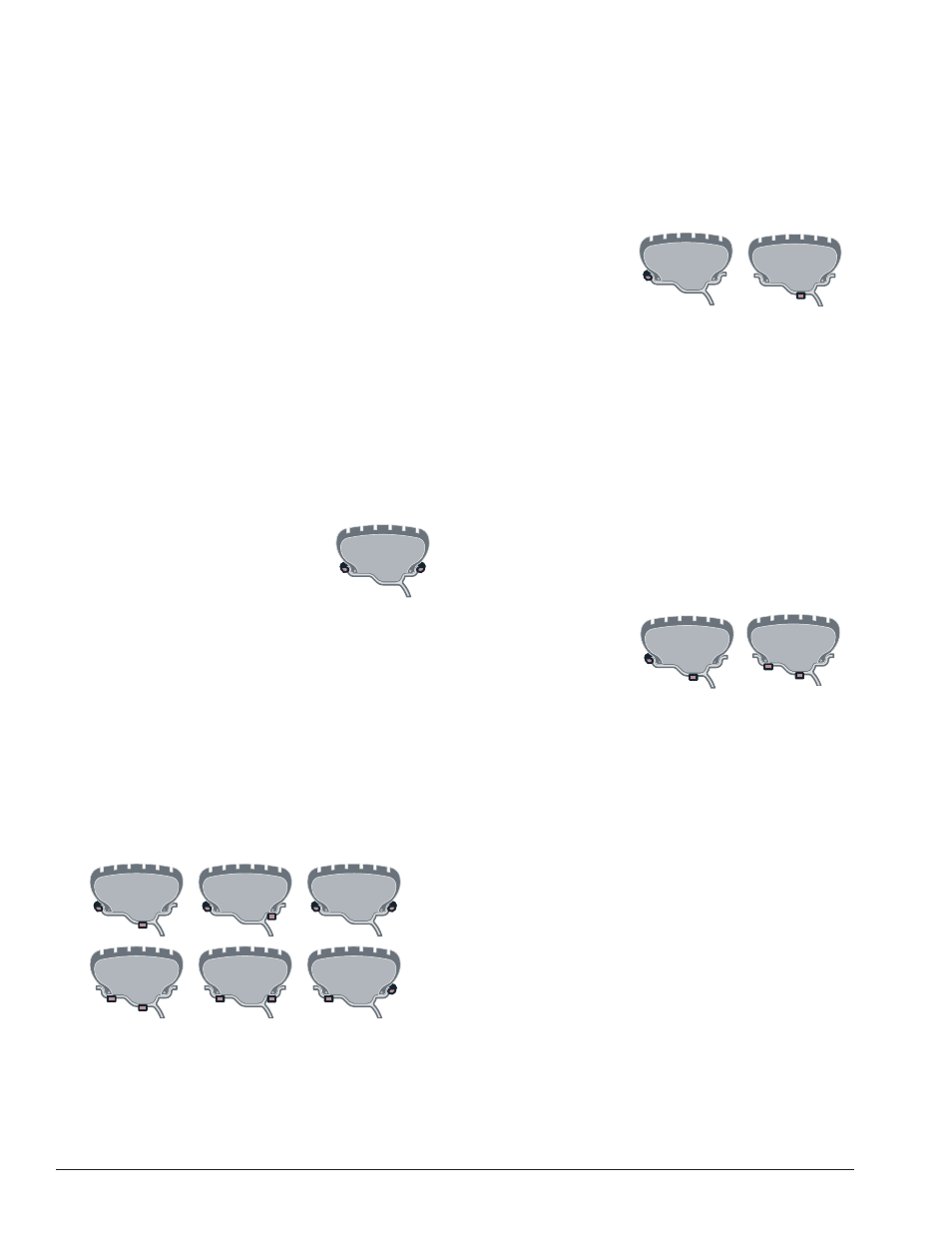
Dynamic Balancing
Choose a dynamic balance to balance a wheel using
two planes for correction. Direct Select™ the weight
option that best fits the available weight locations.
Clip-on Weights -The default; used for most passen-
ger and light truck tire assemblies using the most com-
mon location for corrective weights. Clip-on weights
are placed on the inner and outer rim flanges.
Have the following items handy: appropriate style clip-
on weights.
Direct Select Weight position Clip 1
and Clip 2 (weight locations illuminate).
At these locations place the corrective
weight amount at top-dead-center.
Tape-A-Weights
®
and Hidden Tape-A-Weights
®
-
Used when one or both clip-on weight locations are not
possible or desired. Select the weight location(s) that
best fits the rim configuration.
Have the following items handy: appropriate style clip-
on weights and Tape-A-Weights
®
.
Direct Select Weight position Clip 1 or T1 - Tape and
T2 - Tape, T3 - Tape or Clip 2 (weight locations illumi-
nate). At all locations, except T-2 Tape, place the correc-
tive weight amount at top-dead-center. If the T2 - Tape
weight location is selected, the balancer activates its
Laser Guided Operation™ feature (see page 6).
Static Balancing
Choose a static balance for wheel assemblies that
are not possible to balance dynamically or for narrow
wheels. For example, a motorcycle wheel that has a
small wheel width.
Have the following items handy: an appropriate wheel
assembly mounted on the balancer and a selection of
weights.
When in static mode,
the active Direct Select
Weight location is Clip 1
or T2 - Tape. Select the
weight location(s) that
best fits the rim configuration.
At the Clip 1 location, place the corrective weight
amount at top-dead-center. If the T2 - Tape weight loca-
tion is selected, the balancer activates its Laser Guided
Operation™ feature (see page 6).
Note: If using a patch weight, refer to Patch Weight
Balance, page 13.
Special Balancing Modes
A special balancing mode is required for the following
methods.
Behind Spoke (T2 - Tape Mode Only) - Used to
balance with two adhesive weights located behind the
spokes in the outer correction plane.
Only use the Direct
Select Weight position
Clip 1 or T1 - Tape and
T2 - Tape (weight loca-
tions illuminate). When
the T2 - Tape weight location is selected, the balancer
activates its Laser Guided Operation™ feature (see
page 6).
Begin by following the Laser Guided Operation™ pro-
cedure, steps 1 through 4 on page 6.
1
. When unbalance is displayed, rotate wheel until
inboard center bar blinks. Attach inboard corrective
weight at top-dead-center.
2
. Next, rotate wheel until the outboard center bar
blinks and the two bars on either side blink.
Note: The laser locator dot will stop blinking.
3.
Select the BEHIND SPOKE mode option.
Important: Be sure that the Spoke 1 and Spoke 2
locations are on either side of the original outboard cor-
rective weight location, as shown in figure 15.