Caution – COATS 6450 3D User Manual
Page 12
6 • Important:
Always read and follow the information box instructions.
Laser Guided Operation™ System
The operator must select T2 - Tape Laser Locator to
activate the Laser Guided Operation™ feature, see page
8 for the button selection. This Direct Select™ weight
location is used when placing hidden adhesive weights
at the inner area of the wheel and is the required weight
location selection for the Behind Spoke mode.
Follow these steps to use the Laser Guided Opera-
tion™ feature for accurate placement of hidden Tape-
A-Weights
®
:
Important: Only use the Direct Select Weight posi-
tion Clip 1 or T1 - Tape
and T2 - Tape (location
illuminated). Refer to
Using The Offset Arm
on page 4 and Using
The Lasers on page 5.
1.
Begin by mounting the wheel assembly.
2.
Be sure to Direct Select™ T2 - Tape as the out-
board weight location (refer to Dynamic Balance, Hid-
den Tape-A-Weights, page 12).
Note: The laser locator dot activates and blinks.
3.
Rotate the laser locator knob to position the laser
locator dot at the desired weight location. See figures
8 & 7B.
Note: For best performance, choose a weight position
outboard as far inward (in the rim) as wheel allows.
4.
Enter the A & D wheel measurements, wait for
BEEP. Then, before returning arm to home position,
move arm to inner area of wheel and position the line
laser beam at the T2 - Tape laser locator dot position;
wait for BEEP.
5.
Lower hood; wheel spins.
6.
2D Model - When wheel comes to a complete
stop, manually rotate wheel until the inboard center bar
blinks. Attach inboard corrective weight at top-dead-
center.
3D Model - Wheel will come to a complete stop at
the inboard weight position, center bar blinks. Attach
inboard corrective weight at top-dead-center.
Note: If an inboard corrective weight is not required
then the wheel will stop at the outboard corrective
weight location.
7.
2D Model - Manually rotate wheel to outboard cor-
rective weight location where the outboard center bar is
steady and the two bars on either side blink.
3D Model - Press NEXT to rotate wheel to outboard
corrective weight location where the outboard center
bar is steady and the two bars on either side blink.
Note: The laser locator dot will stop blinking.
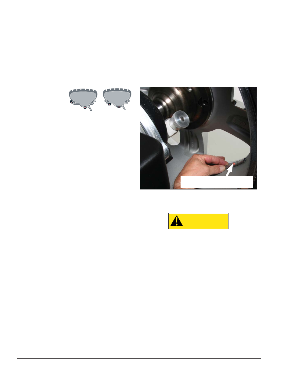
8.
Center and attach the outboard corrective weight
at laser locator dot location as shown in figure 11.
9.
Respin tire/wheel to check balance.
Figure 11 - Centering Corrective Hidden Weight At Laser Loca-
tor Dot Location
3D - Auto Wheel Positioning
CAUTION
Keep hair, loose clothing, fingers and all
parts of body away from moving parts.
The balancer’s auto positioning feature stops the
wheel automatically at the corrective weight location.
The wheel is spun and unbalances are measured and
displayed. The inboard center bar blinks as the balancer
stops the wheel at the inboard corrective weight loca-
tion (top-dead-center). (If an inboard corrective weight
is not required then the wheel will stop at the outboard
corrective weight location.) Press NEXT. The outboard
center bar blinks as the wheel automatically moves and
stops at the outboard corrective weight location (top-
dead-center).
Pressing NEXT moves the wheel automatically to the
next corrective weight location. Pressing EXIT releases
the wheel so that it can be manually positioned.
After several minutes of inactivity, the auto position-
ing feature will turn it self off. Press NEXT to make the
feature activate again.
Center Corrective Weight At
Laser Locator Dot Location