Video balancer, Balancing your first tire – COATS Series XR 1750, 1750-2D, 1750-3D, 1750-3DI Balancer User Manual
Page 8
2 •
Important: Always read and follow the on-screen operating instructions.
Video Balancer
Balancing Your First Tire
Important: Always read and follow the on-screen
operating instructions.
1. Turn the machine OFF then ON
(resets machine).
The initial screen is in dynamic mode using standard
clip-on wheel weight locations and wheel dimensions.
2. Mount a tire/wheel on the
balancer that will use standard clip-
on wheel weights.
Use the most appropriate mounting method.
3. Always remove any weights
already attached to the wheel.
Use the most appropriate mounting method. Always
remove any weights attached to the wheel.
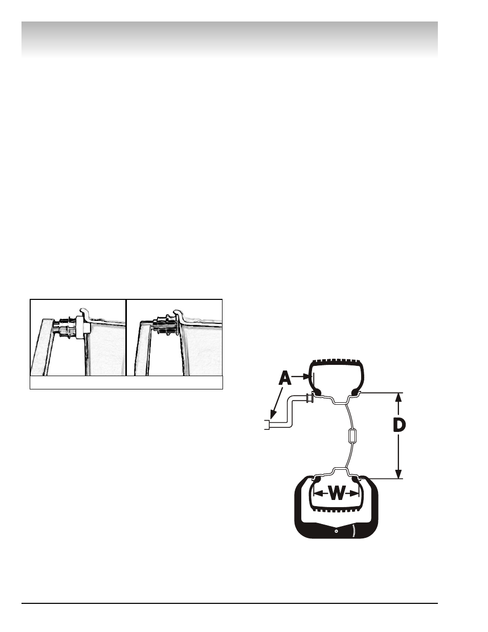
4. Enter A & D wheel dimensions
using offset arm.
For Automatic Measurement — pull the offset arm
out to the wheel, hold it still at clip-on weight position
against the wheel flange, and wait for the BEEP.
Clip-on Weight Location — viewed on a cut-away rim
for clarification.
5. Enter Width wheel dimension.
Enter Width at DIM screen or, if equipped with the
Hood Sensor System, lower the hood to automatically
measure tire width.
6. The wheel spins and unbalances
are measured and displayed.
The corrective weight amount appears on the video
display screen for the left and the right planes of the
wheel, see figure 3.
7. Raise hood after tire stops
rotating.
Note: If the hood is raised before the end of the
spin, an error screen will appear. Wait for the weight
amounts to display before raising the hood.
8. Rotate wheel to position left side
placement arrow at the center bar.
As illustrated in figure 3, rotate the wheel to position
the left side placement arrow at the center red bar.
Step on the positioning pedal to hold the tire in place.
9. Attach left side corrective weight
amount at top-dead center on the
inside flange of the wheel.
Attach specified corrective weight amount (0.25 oz in
figure 3) at top-dead-center on inside flange of wheel.
10. Rotate wheel to position right
side placement arrow at center bar.
Rotate the wheel to position the right side placement
arrow at the center red bar. Step on the positioning
pedal to hold the tire in place.
11. Attach the right side corrective
weight.
Attach specified weight amount (0.75 oz in figure 3) at
top-dead-center on the outside flange of the wheel.
12. Lower the hood to respin the
tire/wheel and check balance.
Your weight readings should now be 0.00.
Note: Throughout this manual tire dimensions are
referred to as A, W, and D, see figure 2.
Figure 2 - A, W, and D Tire Dimensions
Metal Offset Arm
Plastic Offset Arm
Figure 1 - Automatic Measurement