3 transmitter input definitions, 3 transmitter input definitions -6, Figure 51 transmitter sensor terminals -6 – CiDRA SONARtrac HD GVF-100 User Manual
Page 59
Copyright © 2006 CiDRA Corporation
Page 9-6
20675-02 Rev 01
9.3
Transmitter Input Definitions
Entrained Air calculations use inputs of pressure and temperature.
These inputs can be made through the use of pressure and
temperature transducers, or alternatively, an assumed value for
pressure and temperature can be input into the transmitter during its
setup.
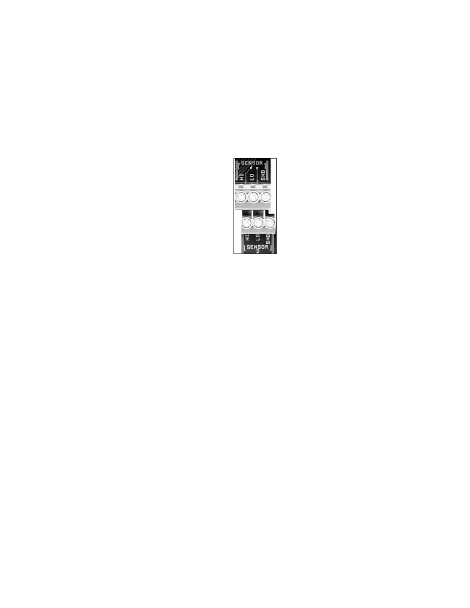
Two transmitter terminal blocks (shown below) are provided for
pressure and temperature transducers.
Figure 51
Transmitter Sensor Terminals
SENSOR 1 & 2
– Used in certain installations for inputs from user-
supplied loop powered 4-20mA pressure or temperature transmitters
which the SONARtrac
TM
transmitter supplies with a nominal +24V.
The pressure or temperature transmitter electrical connections must
be isolated from ground ("floating"). Note that per the SONARtrac
System Control Drawing (CiDRA 20332-01, found in Appendix C)
these connections are not non-incendive field wiring and there
are no entity parameters provided. In general, this means that
these inputs cannot be directly connected to pressure or
temperature transmitters located in Class I, Division 2 locations
or any other hazardous (classified) locations unless additional
precautions as defined by the pressure or temperature
transmitter manufacturer are taken (e.g. zener barriers). See the
Class I, Division 2 installation instructions provided by the
manufacturer of the pressure or temperature transducers and
those of the zener barrier manufacturer for guidance in achieving
a safe installation.