Caution – CiDRA SONARtrac HD GVF-100 User Manual
Page 32
Copyright © 2006 CiDRA Corporation
Page 7-14
20675-02 Rev 01
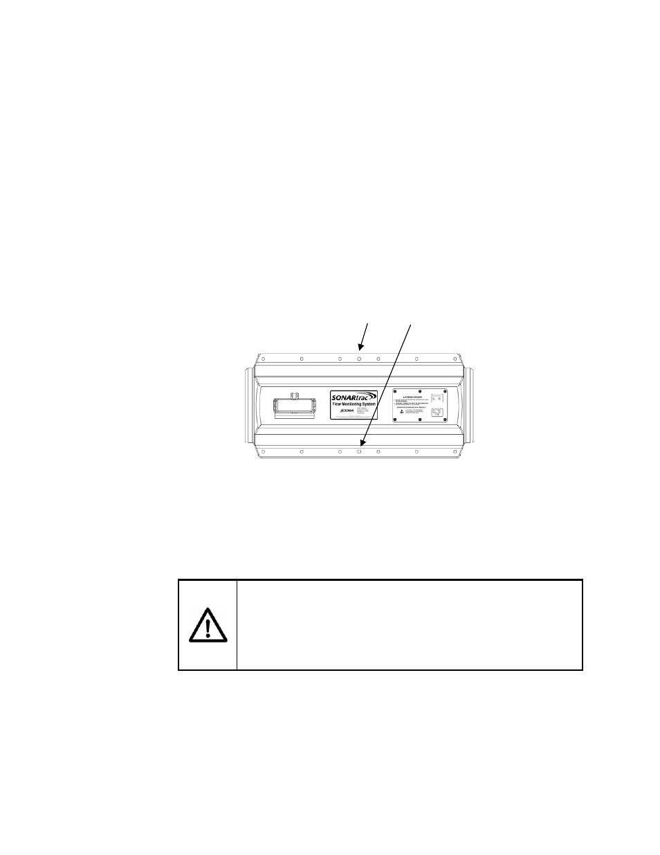
10
6
2
4
8
11
7
3
1
5
9
12
Alignment bolts
Tighten the alignment bolts 2 – 3 turns alternating between both sides
of the cover until the cover bolts protrude through the lower cover
assembly. Note: Use of the alignment bolts may not be necessary if
the cover bolts and nuts can be made up.
Place a washer, lock washer and nut on the end of the sensor cover
bolt once it is through both halves of the cover and begin drawing the
cover halves together using the cover bolts. It is no longer necessary
to use the alignment bolts to draw the cover halves together.
Continue tightening the sensor cover bolts 1 - 2 turns in the tightening
sequence shown in Figure16. The gasket on the cover will compress
and the cover assembly halves will pull together. Tighten the cover
bolts until the two halves of the cover are drawn together so that there
are no gaps along the axis of the cover. Note: There may be some
small gaps between the cover halves in between the bolts; this is
normal.
Figure 18
Sensor Cover Bolt Tightening Sequence
Note:
The gaskets on the cover assembly will compress and conform
to the pipe surface during installation. Upon removal the gasket will
relax a little and will provide proper sealing if re-installed at the same
location from where it was removed.
CAUTION
The sensor cover gasket on fiberglass covers should be
replaced, if the assembly is moved to another pipe, to minimize
the potential for water leakage into the cover. Refer to rework
instructions (RI-0001) for information.
Following installation of the cover fasteners remove the alignment
bolts.