Figure 35 terminal board layout -4, Warning – CiDRA SONARtrac HD GVF-100 User Manual
Page 45
Copyright © 2006 CiDRA Corporation
Page 8-4
20675-02 Rev 01
WARNING
Transmitter cover screws must be securely tightened and NEMA
4X rated cable glands and hole plugs must be used in Class I
Division 2 applications. Failure to do so may result in violation
of Class I Division 2 certification.
8.4.2
Transmitter Output, Sensor and Sensor Head Connections
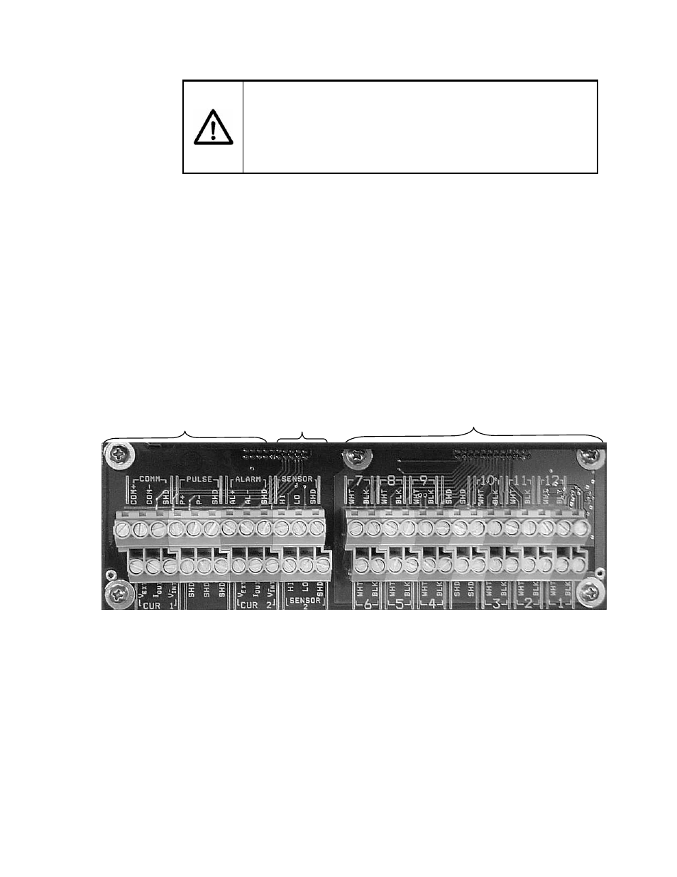
The following figure shows the layout of the transmitter terminal strip
board. This board is divided into three sections.
The Section#1 terminal blocks are for transmitter outputs.
The Section #2 terminal blocks are for external sensor inputs
(pressure and temperature).
The Section #3 terminal blocks are for the cable interface to the
sensor head. This consists of 12 twisted pairs of conductors plus a
cable drain wire (shield). For Class I, Division 2 rated versions these
are to be treated as non-incendive field wiring.
Figure 35
Terminal Board Layout
Section #3
Section #1
Section #2