2 dc-powered sonartractm, Figure 43 transmitter power connection -11, Warning – CiDRA SONARtrac HD GVF-100 User Manual
Page 52: Caution
Copyright © 2006 CiDRA Corporation
Page 8-11
20675-02 Rev 01
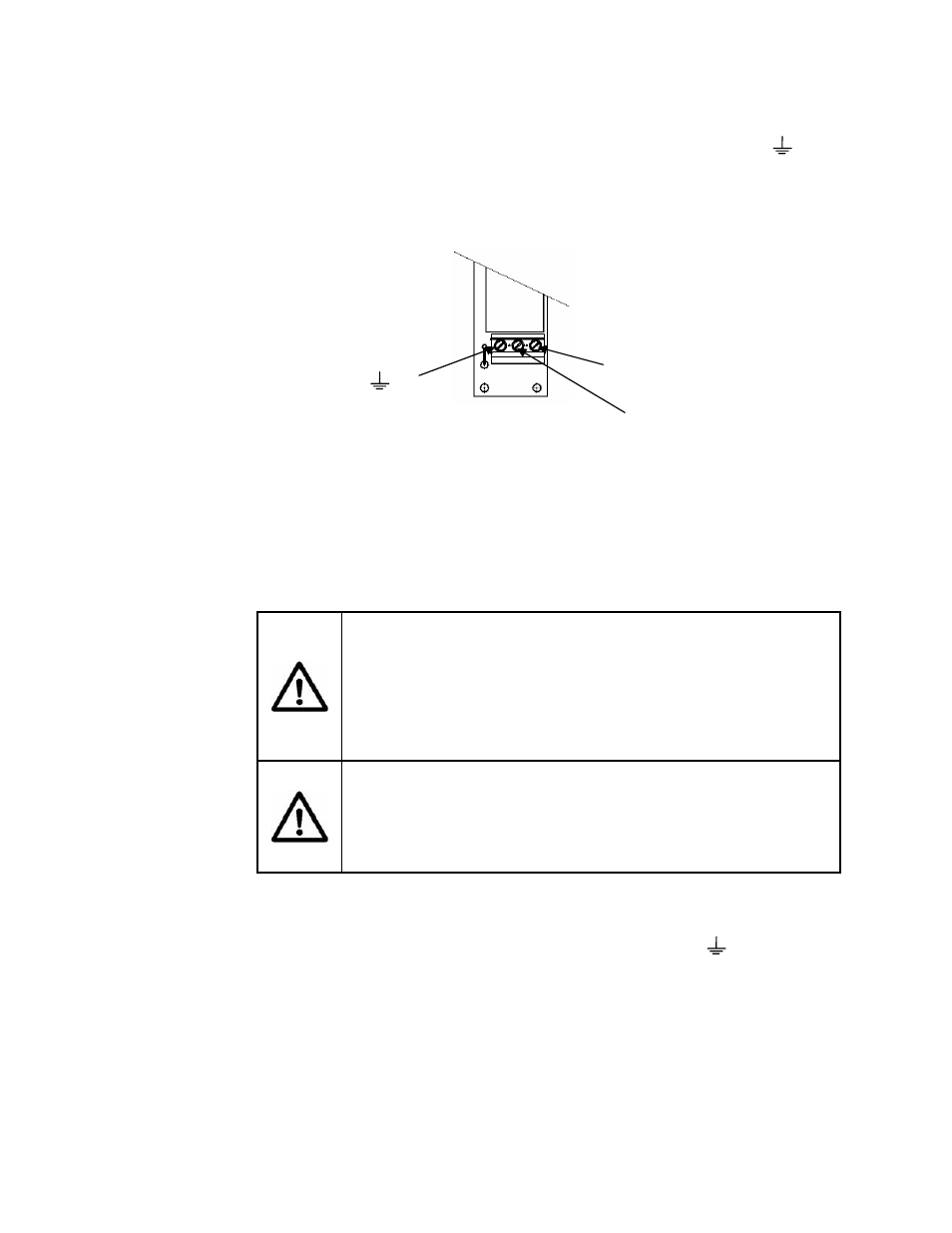
Feed electrical power wires through the fitting. Referring to the
following figure, attach the ground wire (green) to the Ground ( )
terminal , hot (black - U.S., brown - Eur) to the L (+) terminal, and
neutral (white – U.S., blue – Eur) to the N (-) terminal.
Figure 43
Transmitter Power Connection
8.4.3.2 DC-Powered
SONARtrac
TM
Any voltage within the range of 18 – 36 VDC can be applied to the DC
version of the SONARtrac
TM
. Power cables of size 18-gauge
(minimum) to 10-gauge (maximum), with a ground conductor, are
required.
WARNING
For Class I, Division 2 installations, a non-current carrying safety
ground attached to the ground terminal on the input power
terminal block is required, and Power Entry and Inputs/Outputs
must be installed in accordance with Article 501.10(B)(1) of the
National Electrical Code ANSI/NFPA 70:2005.
CAUTION
Always use a non-current carrying safety ground attached to the
ground terminal on the input power terminal block. Failure to do
so could result in poor system operation.
Feed electrical power wires through the fitting. Referring to the
previous figure, attach the ground wire to the Ground ( ) terminal,
DC+ to the L (+) terminal, and DC- to the N (-) terminal.
Line In (+)
Neutral (-)
Ground (
)