CiDRA SONARtrac HD GVF-100 User Manual
Page 25
Copyright © 2006 CiDRA Corporation
Page 7-7
20675-02 Rev 01
1 2
3 4
5 6
7 8
9
Sensor band assembly
Start with the center most screw and tighten screws, alternating from
side to side, 3 - 4 turns at a time. Refer to the following figure for the
screw tightening sequence. Note: Repeat the tightening sequence
only until the Belleville disc springs on the screws begin to compress.
Figure 8
Sensor Band Screw Tightening Sequence
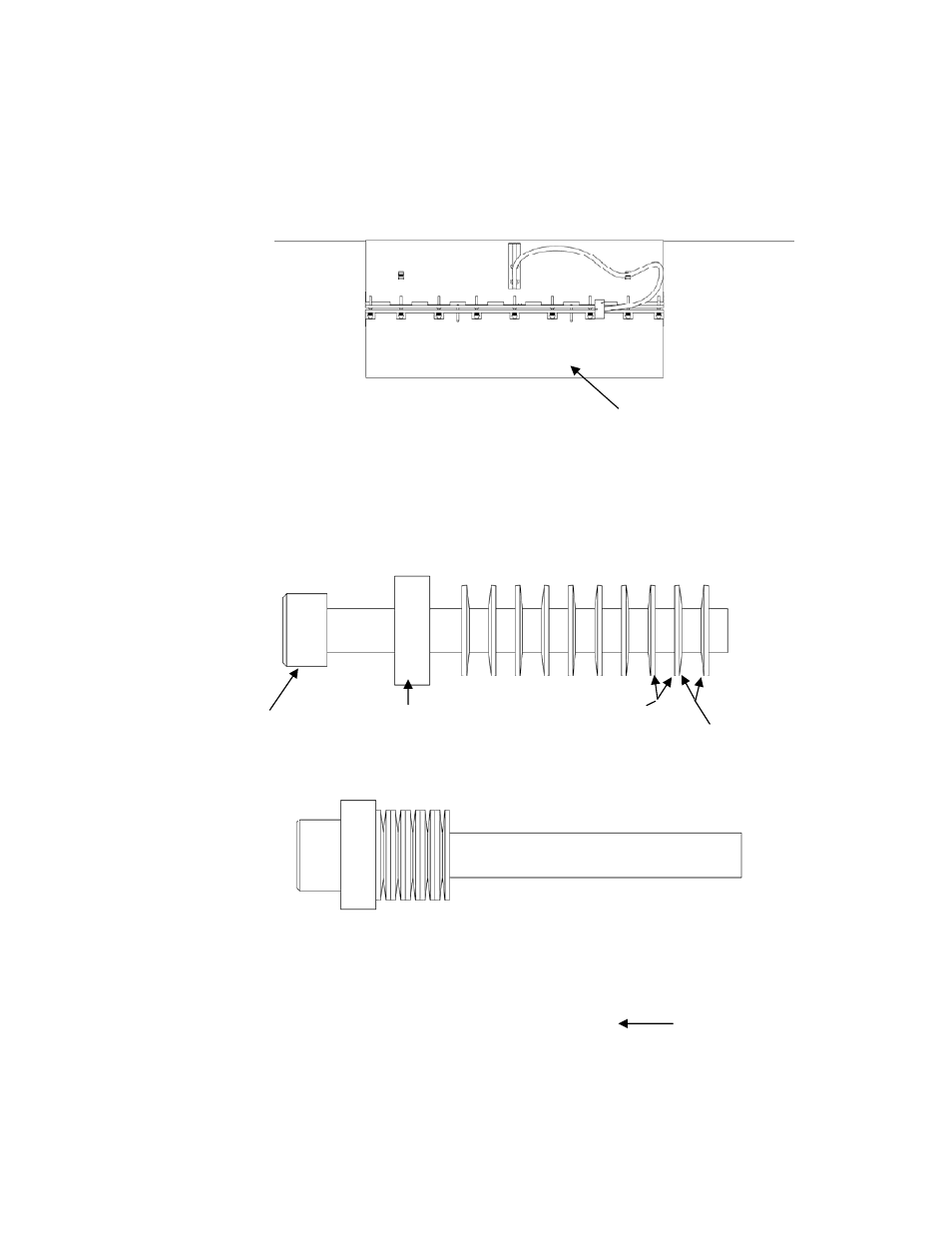
The sensor screw stack up assembly is illustrated below.
Figure 9
Sensor Band Screw Assembly
Sensor screw
Sensor screw spacer
(may be integral to
screw head)
Sensor Belleville washers
convex side
Sensor Belleville washers
concave side
Belleville washers and spacer
compressed against screw head
) ( ) ( ) ( ) ( ) ( ) ( ) (
Note: Sensor bands 18” and
larger have 14 Belleville washers
per screw arranged as shown
Note: 10 Belleville Washers on 2-16” bands