4 transmitter cable connections, 1 transmitter housing cable entry, 4 transmitter cable connections -3 – CiDRA SONARtrac HD GVF-100 User Manual
Page 44: 1 transmitter housing cable entry -3
Copyright © 2006 CiDRA Corporation
Page 8-3
20675-02 Rev 01
8.4
Transmitter Cable Connections
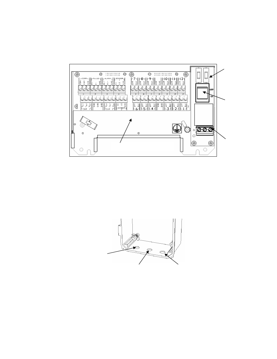
The following figure illustrates the basic power and signal connections
for the SONARtrac
TM
VF & GVF Monitor. These are discussed in
further detail in the following sections.
Figure 33
Power and Signal Interconnects
8.4.1
Transmitter Housing Cable Entry
Power, sensor signal, and input /output signal cables enter the
transmitter housing through cable glands. The cable glands also
provide strain relief for the cables. Always ensure they are fully
tightened. The following figure illustrates where each of the cable
glands are installed.
Figure 34
Transmitter Housing Cable Gland Holes
Note:
On those transmitters installed in Class I Division 2 areas,
cable glands rated for NEMA 4X (minimum rating) must be used. Any
unused cable gland holes must be sealed with NEMA 4X rated hole
plugs. Also, the four cover sealing screws on the transmitter cover
must be securely tightened in order to ensure a proper seal.
Output & Sensor
cable gland hole
Sensor head to transmitter
cable gland hole
Power cable gland hole
Fuses
Optional
power
switch
Power
connector
I/O and sensor connects