3 sensor assembly cable connection, 3 sensor assembly cable connection -19 – CiDRA SONARtrac HD GVF-100 User Manual
Page 37
Copyright © 2006 CiDRA Corporation
Page 7-19
20675-02 Rev 01
Figure 27
Boot Gasket Fender Assembly
7.6.3
Sensor Assembly Cable Connection
Remove the tape (if it was used) that was temporarily installed to
retain the sensor connector under the cover access panel. Remove
the factory installed shorting plug from the sensor cable connector.
Place the shorting plug in the holder in the transmitter housing. (It will
be used if sensor removal from the pipe is necessary.) Install the
sensor assembly cable connector into the mating receptacle located
inside the access cover plate on the sensor upper cover as shown
below. The connector is installed such that the connector key faces
away from the pipe. Push the connector into the mating receptacle.
The locks on the receptacle will engage to keep the plug from pulling
out. Ensure the connector is fully engaged. Note: Use care to ensure
the sensor cable connector goes on squarely to minimize risk of
damaging the contacts.
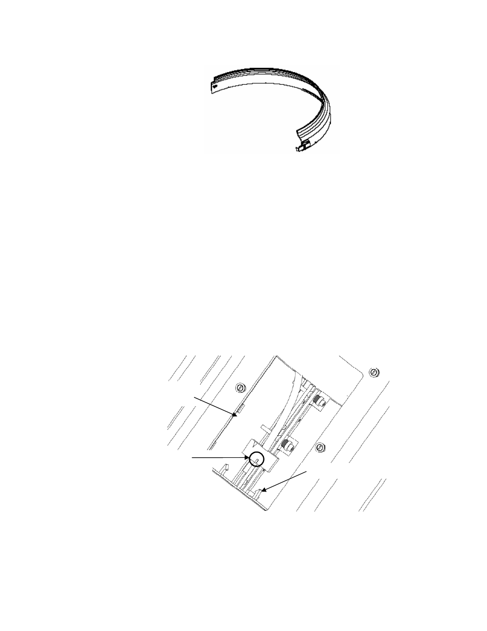
Figure 28
Sensor Assembly Cable Installation
Connector locks
Sensor cable
access port
Sensor cable with key
positioned up away from pipe