1 sensor band short test, 2 sensor band thermal barrier installation, 1 sensor band short test -10 – CiDRA SONARtrac HD GVF-100 User Manual
Page 28
Copyright © 2006 CiDRA Corporation
Page 7-10
20675-02 Rev 01
7.5.1
Sensor Band Short Test
Shorting of the sensor band to the process pipe may cause signal
interference or electrical faults in the system in some instances. The
sensor band must be electrically isolated from the process pipe.
Use an ohm meter and verify the sensor band is isolated from the
pipe. Measure the resistance between the sensor rails and the pipe to
ensure there is no continuity between the sensor band and the
process pipe. If the band is shorted identify where the short is located
and eliminate the short. For example, if a sensor screw is shorting to
a pipe weld bead, reposition the sensor band, or lightly file the weld
bead to eliminate the interference.
7.5.2
Sensor Band Thermal Barrier Installation
Install the sensor band thermal barrier if one was included with the HD
VF-100 System. Refer to the figure below.
1. Align the slit on the thermal barrier with the sensor band to pre-
amplifier cable.
2. Wrap the thermal barrier over the sensor attachment rails.
3. Continue to wrap the thermal barrier around the sensor band.
4. Seal at the Velcro strips and install the straps through the D-rings
on the thermal barrier.
5. Retain the sensor ban to pre-amplifier cable in the Velcro retention
loop.
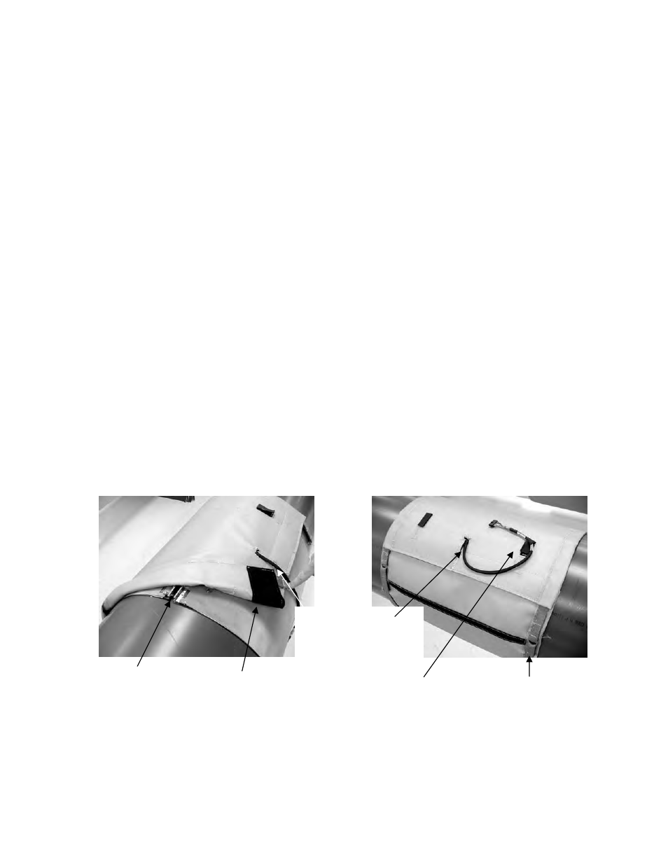
Figure 13
Thermal Barrier Installation Over Sensor Band
Mounting rails on top of
pipe covered with
thermal barrier
Velcro strip for sealing
thermal barrier
Sensor band to pre-
amplifier cable in slot on
thermal barrier
Sensor band to pre-
amplifier cable in
retention loop
Thermal barrier
straps (both sides)