Model c001 tool use -17 – CiDRA SONARtrac HD GVF-100 User Manual
Page 35
Copyright © 2006 CiDRA Corporation
Page 7-17
20675-02 Rev 01
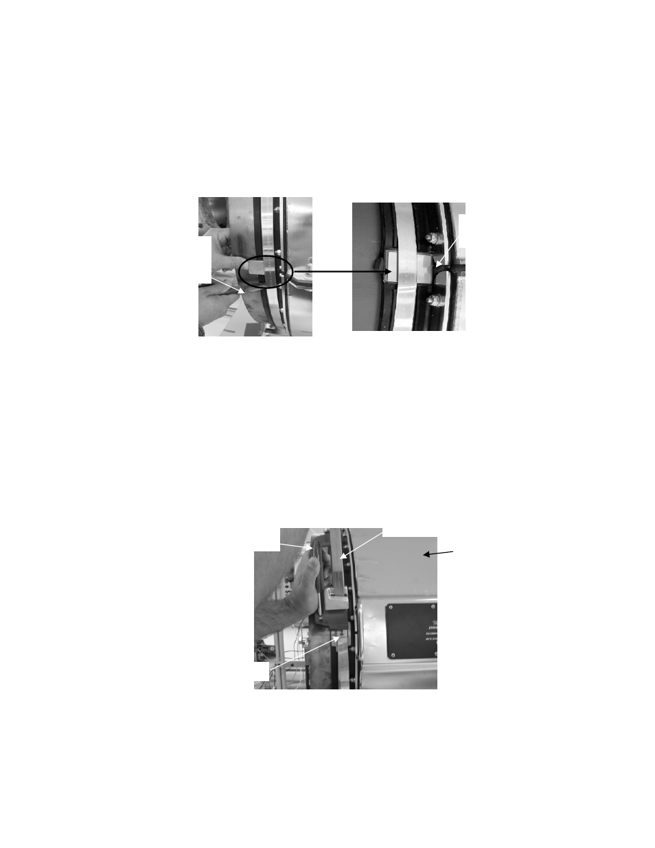
Remove the GelTek paper backing from the splice protector plate, lift
the band using needle nose pliers or a screwdriver, and slide the plate
into position over the flange gasket. Be careful the GelTek stays in
position on the plate. Pull the band taut. Tighten the socket head cap
screw on the band buckle just enough to keep the band in place but
loose enough so it will still slide through the buckle. Repeat on the
opposite end of the cover.
Figure 23
Splice Protector Plate Installation
Install the BAND-IT
®
Model C001
tensioning tool by inserting the band
through the cutter bar and slide lock.
Note:
This tool is asymmetric. The tool will pull in opposite directions
when installed on opposite ends of the cover. The cutter handle
(positioned either up or down) on the Model C001 is located outboard
with respect to the cover end when the tool is properly installed. The
following figure illustrates proper installation of the tool.
Figure 24
BAND-IT
®
Model C001 Tool Use
Verify the band is still aligned within the grooves on the boot gasket
and over the first wrap of the band, and the band buckle is positioned
over the gasket protector plate.
Lift band with
needle nose pliers
or screw driver
Splice protector plate
centered on gasket splice
Tensioning tool cutter
handle outboard of cover
Excess band material
Band buckle
SONARtrac
TM
cover