CHAMPION USN72 User Manual
Page 188
4
Table Limit Switch (TLS) Installation Instructions
Section 4: Assembling the Table Limit Switch
1. Refer to Fig. 4, TLS and Mounting Bracket, below.
Part (A) is the switch body, Part (B) is the actuator head/nylon rod installed on the switch body,
and Part (C) is the bracket which mounts the TLS assembly to the back of the dish table. The long
screws attach the TLS to the bracket and the short screws mount the bracket to the dish table.
Refer to Fig. 5, Assemblying the TLS below.
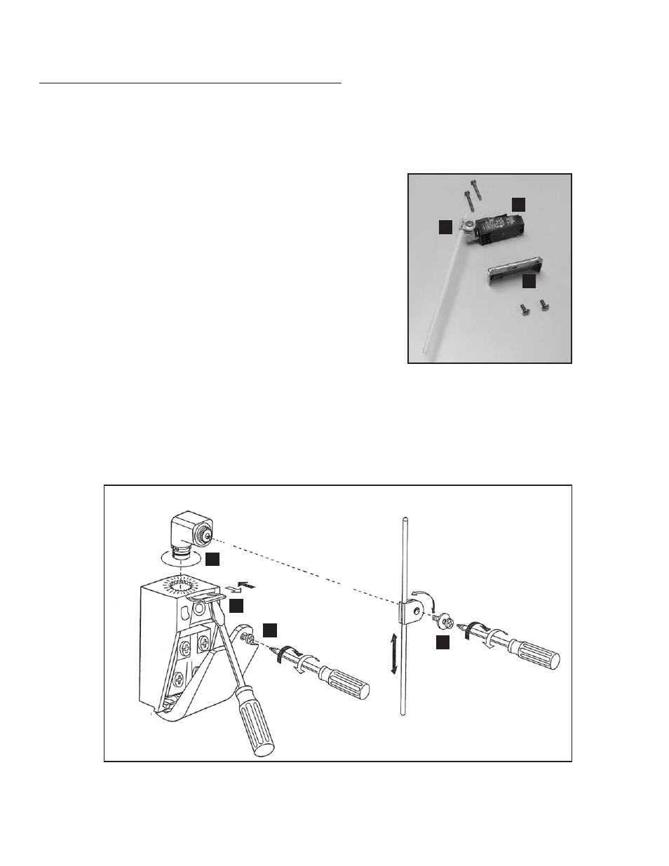
To assemble the TLS:
a. Remove Screw (A) and remove the TLS cover.
b. With a flat blade screwdriver, gently pull the
Retaining Clip (B) forward.
c. Insert the Actuator Head (C) into the switch body then push
the retaining clip back into place to hold the actuator.
d. Screw the Clamp with Nylon Rod (D) to the actuator head.
Fig. 4 -
TLS and Mounting Bracket
A
B
C
Fig. 5 -
Assembling the TLS
A
B
C
D