C57 modified electrical connections – CHAMPION USN72 User Manual
Page 173
11
USN72 Booster Conversion Instructions - Kit P/N 453393
C57 Modified Electrical Connections
1. Refer to the Installation &
Operation Manual for the
electrical specifications for the
C57 Modified booster and connect
the incoming power service at
the main terminal block located
on the left-side of booster cabinet.
2. Refer to the wiring diagram at the
bottom of this page and connect
the Low Temperature Interlock wires
that were previously removed from the
Champion CH-60 booster.
3. The Low Temperature
Interlock connection block
is located on the right-side of the
booster cabinet.
4. Close the booster cabinet and
refer to the Installation and
Operating Manual for the
C57 Modified booster.
Main
Terminal
Block
The main terminal block is located on the left-side
of the booster cabinet interior.
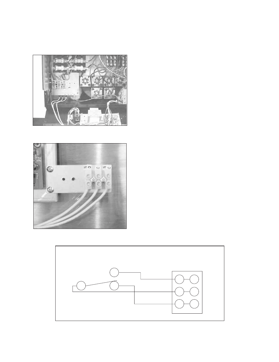
The Low temperature interlock block is located on
the right-side of the booster cabinet interior.
NO
NO
NC
COM
COM
NC
TEMPERATURE INTERLOCK
Low Temperature Interlock Switch Wiring Diagram