9 engine coupler, 1 coupler removal, 2 coupler installation – JLG G6-23A Service Manual User Manual
Page 69: Engine coupler, Coupler removal, Coupler installation
7.9
G5-19A, G6-23A
Engine: Deutz BF 4M 2012
If the rpm is not 2370 ±50 rpm, readjust the throttle
limit-stop screw at the throttle pedal within the cab.
21. Purge the hydraulic system of air by operating all
boom functions through their entire range of motion
several times. Check the hydraulic oil level.
22. Check for proper operation of all components.
23. Turn the engine OFF.
24. Install the belly pan.
25. Install the engine cover. Close and secure the cover.
7.9
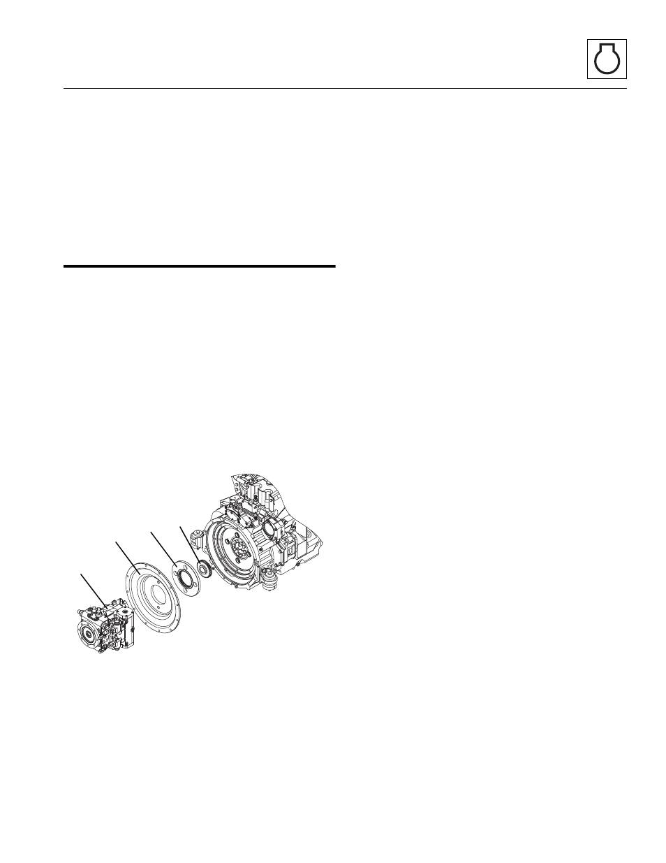
ENGINE COUPLER
7.9.1
Coupler Removal
1. Remove Hydrostatic transmission (3). Refer to
Section 6.4.1, “Transmission Removal.” Be sure to
follow all described safety guidelines.
2. After transmission has been removed, take out the
12 bolts that attach the Flywheel Cover Plate (4) to
the engine.
3. Pull off the Flywheel Cover Plate to expose the
coupler (5) and the flywheel.
4. Remove the necessary bolts to detach the coupler
and flex plate (6).
7.9.2
Coupler Installation
1. Attach the coupler (5) and flex plate (6) using the
necessary bolts. Torque to 155 lb-ft (210 Nm).
2. Bolt on the Flywheel Cover Plate (4) over the coupler
and flywheel. Torque bolts to 37 lb-ft (50 Nm).
3. Reattach the hydrostatic transmission (3). Follow all
guidelines in Section 6.4.3, “Transmission
Installation.”
MAH0630
3
4
5
6