JLG G6-23A Service Manual User Manual
Page 41
4.9
G5-19A, G6-23A
Cab and Covers
Note: Label all hoses to ensure correct installation.
8. Loosen the hose clamps, and disconnect the heater
hoses from the engine. Cap or plug the hoses to
prevent debris from entering the heater system.
9. Disconnect the cab-to-wiring harness connectors.
Note: Record the location, and label all cables to ensure
correct installation.
10. Working underneath the cab, label and disconnect
the hydraulic hoses at the cab fittings. Plug the
hoses and cap the fittings.
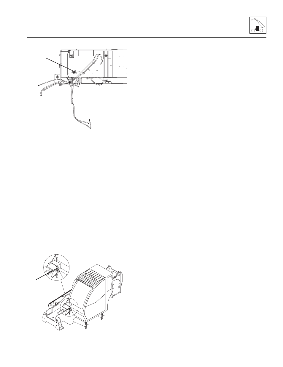
11. Disconnect the throttle cable rod end at the throttle
lever extension bracket (1). Route the cable away
from the cab to prevent damage during removal.
12. Install two lifting eye bolts with a suitable lifting
capacity in the existing threaded holes at the top
corners of the windshield.
13. Remove the cab-to-frame bolts (2), washers and
nuts.
14. Carefully begin to lift the cab. Stop and check that all
wiring, hydraulic hoses and fasteners are
disconnected or removed. Do not damage the fuel fill
tube.
15. When all wiring, hydraulic hoses and fasteners are
disconnected or removed, carefully and slowly lift the
cab and remove it from the frame. Readjust the
position of the sling as needed to help balance the
cab during removal.
16. When the cab is completely clear of the machine,
carefully lower it to the ground. Block up or support
the cab.
17. Inspect the condition of the fittings, clamps, hydraulic
hoses, etc. Replace parts as indicated by their
condition.
18. Inspect and replace other machine parts that are
exposed with the cab removed. Repair or replace as
required.
MAH1140
1
Bottom of Cab
MAH0710
2