2 steering column/valve replacement, 3 brake pedal and valve, Steering column/valve replacement – JLG G6-23A Service Manual User Manual
Page 36: Brake pedal and valve
Cab and Covers
4.4
G5-19A, G6-23A
4.3.2
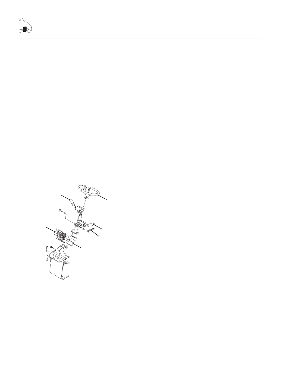
Steering Column/Valve Replacement
a. Steering Column and Valve Removal
1. Park the machine on a firm, level surface, fully
retract the boom, lower the boom, place the
transmission control lever in (N) NEUTRAL, engage
the park brake and shut the engine OFF.
2. Place an Do Not Operate Tag on both the ignition
key switch and the steering wheel, stating that the
machine should not be operated.
3. Open the engine cover. Allow the system fluids to
cool.
4. Disconnect the battery negative (-) cable at the
battery negative (-) terminal.
5. Remove the steering wheel (4) (Refer to Section
4.3.1, “Steering Wheel.”), transmission control lever
(6) and accessory lever (5).
6. Remove the steering column tilt lever (7).
7. Remove the lower dash panel.
8. Label, disconnect and cap the hydraulic hoses (8)
and fittings on the steering orbitrol valve (9).
9. Remove the two pivot bolts for the steering column
and steering orbitrol valve.
10. Pull the steering column assembly from the machine
cab.
11. Remove the four hex-flange capscrews connecting
the orbitrol valve to the steering column.
Note: DO NOT disassemble the steering orbitrol valve.
The steering orbitrol valve is not serviceable and must
be replaced in its entirety, if defective.
b. Steering Column and Valve Installation
1. Install the orbitrol valve onto the steering column.
Torque the four capscrews to 13 lb-ft (18 Nm).
Position the steering valve in the cab, with the ports
pointing toward their original orientation.
2. Secure the assembly with the two pivot bolts.
Note: ALWAYS use new o-rings when servicing the
machine.
3. Uncap and install new o-rings into the fittings.
Lubricate the o-rings with clean hydraulic oil.
4. Uncap and reconnect the previously labeled
hydraulic hoses to their appropriate locations.
5. Install the steering column tilt knob.
6. Install the steering wheel (Refer to Section 4.3.1,
“Steering Wheel.”), accessory lever and
transmission control lever.
7. Connect the battery negative (-) cable to the battery
negative (-) terminal.
8. Carefully examine all connections one last time
before engine start-up. Rectify any faulty conditions.
9. Start the engine and check the operation of all
controls. Check for fluid leaks. Check the hydraulic
fluid level in the tank and add fluid as required.
10. Install the lower dash panel.
11. Close and secure the engine cover.
c. Power Steering Test
Conduct a pressure check of the steering hydraulic
circuits at the test port on the implement pump. Refer to
Section 8.5.5, “Steering Pressure Checking.”
4.3.3
Brake Pedal and Valve
a. Brake Valve Removal
Refer to Section 8.10.2, a. “Service Brake Valve
Removal,” for removal information.
b. Brake Valve Installation
Refer to Section 8.10.2, b. “Service Brake Valve
Installation,” for installation information.
c. Service Brake Pedal Removal
1. Park the machine on a firm, level surface, fully
retract the boom, lower the boom, place the
transmission control lever in (N) NEUTRAL, engage
the park brake and shut the engine OFF.
MAH1100
5
7
8
4
6
9