2 connecting with a hydraulic quick switch device, 4 quick switch removal, 5 quick switch installation – JLG G6-23A Service Manual User Manual
Page 30: Connecting with a hydraulic quick switch device, Quick switch removal, Quick switch installation
Boom
3.8
G5-19A, G6-23A
3.5.2
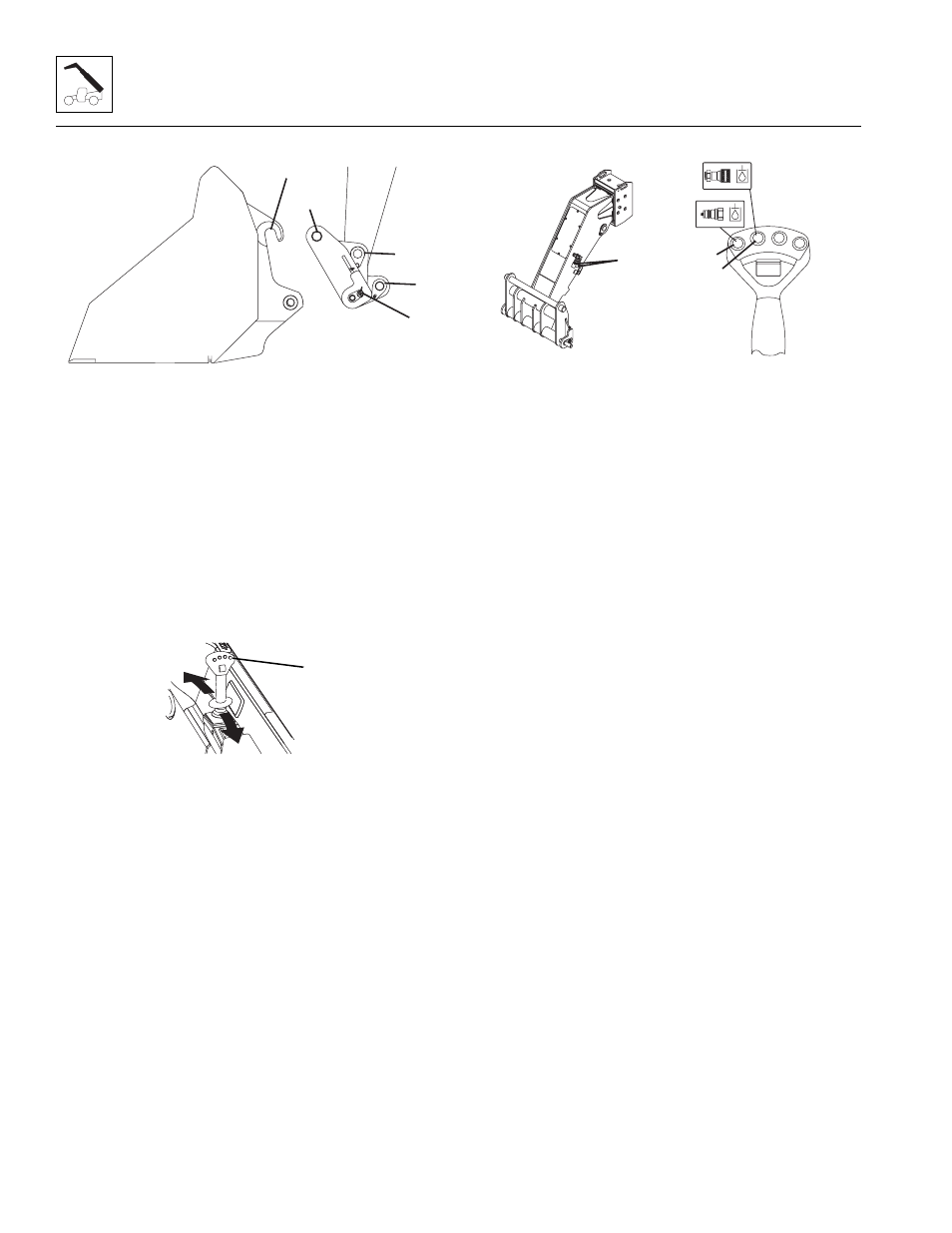
Connecting with a Hydraulic Quick
Switch Device
1. Retract quick switch device to provide clearance.
Check to be sure lock pin is disengaged.
2. Align attachment pin (10) with recess in
attachment (9). Raise boom slightly to engage
attachment pin in recess.
3. Engage quick switch device.
4. Press the button (12) and at the same time, move
the joystick to engage or to disengage the quick
switch device.
5. Raise the boom to eye level and visually check that
the quick switch pin protrudes through the hole. If the
pin does not protrude through the hole, place the
attachment on the ground and return to step 2.
6. If attachment is equipped, connect auxiliary
hydraulic hoses. See Section 3.5.3, “Connecting with
a Quick Switch to a Hydraulic Operated Attachment.”
3.5.3
Connecting with a Quick Switch to a
Hydraulic Operated Attachment
1. Lower attachment to ground and set parking brake.
2. Quickly depress and release button (14) to relieve
pressure at the male auxiliary fitting.
3. Connect to the male auxiliary fitting (13).
4. Quickly depress and release button (15) to relieve
pressure at the female auxiliary fitting.
5. Connect to the female auxiliary fitting (13).
3.5.4
Quick Switch Removal
1. Remove the lock bolt (11) holding the tilt cylinder rod
end pin to the quick switch assembly. Remove the tilt
cylinder pin.
2. Support the quick switch assembly. Remove the pin
from the quick switch assembly from either side.
3. Inspect the above pin for nicks or surface corrosion.
Use fine emery cloth to fix minor nicks or corrosion.
If damaged or if it cannot be repaired the pin must be
replaced.
3.5.5
Quick Switch Installation
1. Assemble the quick switch to the boom head. Line
up the quick switch between the mounts on the
boom head. The quick switch should be centered in
the boom head.
2. Coat the quick switch pivot pin with an anti-seize
compound. Insert the quick switch pivot pin through
the quick switch and boom head.
3. Align the quick switch with the tilt cylinder rod end
and insert the tilt cylinder pin. Align the tilt cylinder
pin and screw in the lock bolt (11). Torque to 72 lb-ft
(97 Nm).
MAH1250
8
9
10
11
11
MAH0980
12
MAH1270
15
14
13