4 hourmeter, 5 coolant temperature sender, Hourmeter – JLG G6-23A Service Manual User Manual
Page 113: Coolant temperature sender
9.23
G5-19A, G6-23A
Electrical System
start the engine. Observe the fuel level indicator
needle on the operator’s instrument cluster.
3. Turn the ignition key switch to the OFF position. The
fuel level indicator needle should return to the
EMPTY position.
b. Fuel Level Circuit Tests
If the fuel level indicator is suspected of giving a false
reading, perform the following checks:
1. If the fuel level indicator needle does not move,
check the fuel tank for fuel.
2. Check for loose or defective wiring, faulty ground
connections or corrosion on the fuel tank sender and
wiring lead.
3. If the fuel level indicator needle does not move after
the ignition key switch is turned to the RUN position,
use a test lamp to determine whether current is
flowing from the ignition switch to the fuel level
sender.
4. If the fuel level indicator does not move and a faulty
or defective fuel level sender in the fuel tank has
been ruled out and in addition, wiring and
connectors have been checked and ruled out, the
fuel level indicator is defective and must be replaced.
5. Check that the ignition terminal has current and that
the fuse in the fuse panel is not blown.
6. Check for broken, shorted, frayed, disconnected or
damaged wiring between the fuel level indicator
wiring at the cab, fuse and relay panel, ignition key
switch and from the fuel level sender on the fuel tank
through the wiring in the cab.
7. Check the fuel level sender. The resistance of the
fuel level sender is 31 ohms for a full tank of fuel,
101 ohms for 1/2 tank and 255 ohms for an empty
tank. A defective fuel level sender in the fuel tank
may also prevent the fuel level indicator from
moving.
9.11.4
Hourmeter
The hourmeter is a non-repairable instrument that
records hours of machine engine operation in tenth of an
hour increments and is located in the instrument cluster.
The hourmeter is an analog device, similar to an
odometer, and will display 99,999.9 hours before
resetting to zero.
If trouble is suspected, time the hourmeter for six minutes
to verify that a tenth of an hour has been recorded.
The hourmeter is built into the instrument cluster and
cannot be repaired. If the hourmeter is suspect, replace
the instrument cluster.
9.11.5
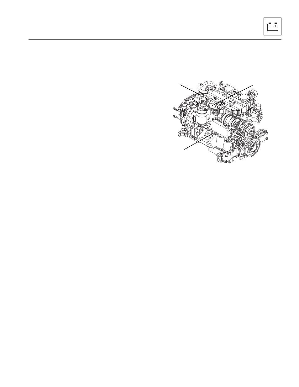
Coolant Temperature Sender
The coolant temperature sender (1) is located on the
back of the engine towards the rear of the machine.
a. Coolant Temperature Sender Removal
1. Open the engine cover. Allow the engine to cool.
2. Disconnect the battery negative (-) cable from the
battery negative (-) terminal.
3. Disconnect the wiring connector at the coolant
temperature sender lead.
4. The coolant temperature sender is threaded into the
engine block. Remove the sender.
b. Coolant Temperature Sender Inspection and
Replacement
Inspect the sender and the wiring harness connector
terminals for continuity. Replace a defective or faulty
sender with a new part.
c. Coolant Temperature Sender Installation and
Testing
1. Thread the coolant temperature sender into the
engine housing snugly, then connect the sender
connector to the wiring harness connector.
2. Connect the battery negative (-) cable to the battery
negative (-) terminal.
3. Check for proper fluid level.
4. Start the engine, allow it to reach operating
temperature and observe the operator’s instrument
cluster for warning indication. If the sender is not
defective, the problem could be elsewhere; possibly
MAH0620
1
2
3