8 electrical system components, 1 back-up alarm, 2 instrument cluster – JLG G6-23A Service Manual User Manual
Page 109: Electrical system components, Back-up alarm, Instrument cluster, Caution
9.19
G5-19A, G6-23A
Electrical System
2. Align the lower alternator mount hole with the lower
mounting bracket on the engine, and insert the lower
mounting capscrew. Be sure to leave enough room
to attach the drive belt.
3. Attach the fan drive belt to the alternator.
4. Adjust the lower belt tensioning bolt to remove
excessive slack from the drive belt. Check for proper
fan belt deflection.
5. Reattach the previously labeled electrical wires to
the alternator.
6. Connect the positive (+) and negative (-) battery
cables to the battery terminals.
7. Close and secure the engine cover.
9.8
ELECTRICAL SYSTEM
COMPONENTS
9.8.1
Back-up Alarm
The back-up alarm is located at the rear of the machine.
When the transmission shift control switch (transmission
control lever) is shifted to the (R) REVERSE position, the
back-up alarm will automatically sound.
Place the transmission control lever in (R) REVERSE to
test the back-up alarm. The back-up alarm must not
sound when the transmission control lever is in (N)
NEUTRAL or (F) FORWARD. Also, with the ignition key
switch in the RUN position, the back-up alarm will sound
when the transmission control lever is shifted into the (R)
REVERSE position.
a. Disassembly
DO NOT disassemble the back-up alarm. Replace a
defective or faulty alarm with a new part.
b. Inspection and Replacement
Inspect the wiring harness connector and alarm terminals
for continuity and shorting. Test the alarm by turning the
ignition key switch to the RUN position and shifting the
transmission control lever into the REVERSE position.
The alarm should sound.
Replace a defective or faulty alarm with a new part.
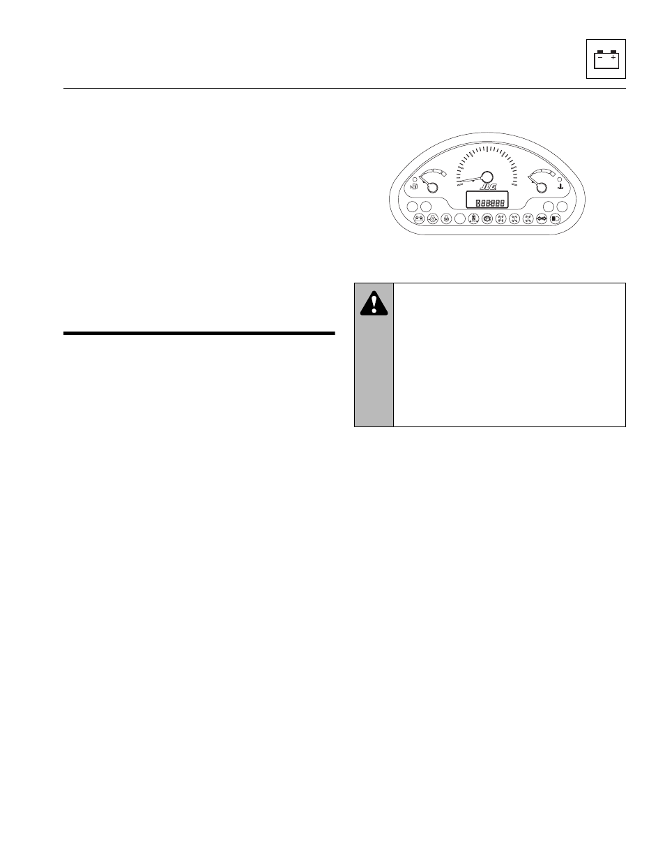
9.8.2
Instrument Cluster
a. Removal
1. Open the engine cover.
2. Disconnect the battery negative (-) cable at the
battery negative (-) terminal.
3. Remove the two nuts holding the instrument cluster
to the dash.
4. Slide the instrument cluster out of the operator
console.
5. Disconnect the wiring harnesses.
b. Installation
1. Connect the instrument cluster wiring harnesses.
2. Position the instrument cluster in the operator
console.
3. Secure to the dash with two nuts.
4. Connect the battery negative (-) cable at the battery
negative (-) terminal.
5. Close and secure the engine cover.
CAUTION:
Static electricity can
cause damage to the operator’s instrument
cluster. Avoid any manner of touching (hands,
tools, etc.) the printed circuit boards and
terminals. Disconnect the battery negative (-)
cable at its battery terminal before beginning
this procedure. Failure to comply can result in
damage to the operator’s instrument cluster
and malfunction of the instruments and
indicator lights.
MAH1090
0
5
10
15
20
25
30
rpm x 100