4 inching valve, Inching valve – JLG G6-23A Service Manual User Manual
Page 37
4.5
G5-19A, G6-23A
Cab and Covers
2. Place an Do Not Operate Tag on both the ignition
key switch and the steering wheel, stating that the
machine should not be operated.
3. Open the engine cover. Allow the system fluids to
cool.
4. Disconnect the battery negative (-) cable at the
battery negative (-) terminal.
5. Remove the lower dash panel.
6. Remove the two capscrews (10) securing the brake
pedal to the inching valve.
7. Remove the circlip (11), flat washer, and the return
spring securing the service brake pedal to the cab.
8. Remove the clip/pin from the brake plunger fork link.
9. Remove the service brake pedal from the cab.
d. Service Brake Pedal Installation
1. Position the service brake pedal in its mounting
location within the cab.
2. Install the brake pedal being careful to reposition the
brake plunger yoke. Install the return spring, washer
and clip. Install clip/pin in brake plunger fork link.
3. Adjust the brake pedal as needed.
4. Install and secure the lower dash cover.
5. Connect the battery negative (-) cable to the battery
negative (-) terminal.
6. Close and secure the engine cover.
4.3.4
Inching Valve
a. Inching Valve Removal
1. Park the machine on a firm, level surface, fully
retract the boom, lower the boom, place the
transmission control lever in (N) NEUTRAL, engage
the park brake and shut the engine OFF.
2. Place an Do Not Operate Tag on both the ignition
key switch and steering wheel, stating that the
machine should not be operated.
3. Open the engine cover. Allow the system fluids to
cool.
4. Disconnect the battery negative (-) cable at the
battery negative (-) terminal.
5. Remove the lower dash panel.
6. Remove the nut holding the inching valve adjusting
rod (12) to the brake pedal bracket (13).
7. Label and disconnect all hoses attached to the valve,
cap all fittings and plug hoses to keep dirt & debris
from entering hydraulic system.
8. Remove the two bolts securing the inching valve to
the inside of the cab.
b. Inching Valve Installation
1. Install the inching valve with the two bolts inside the
cab.
2. Uncap and reconnect the previously labeled
hydraulic hoses to the appropriate locations.
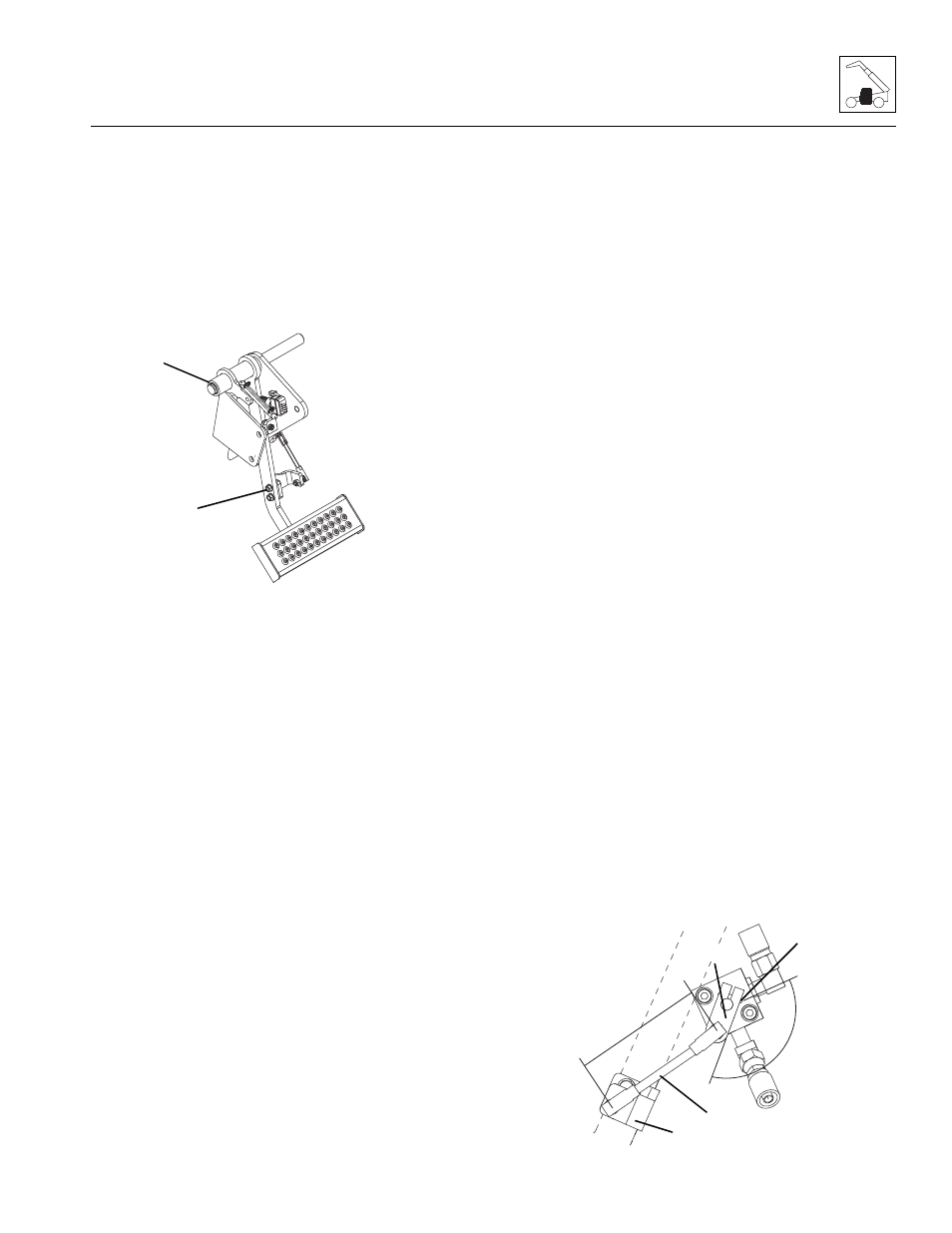
3. Point the pin (14) on the pivoting part of the valve
towards the top T-port. Be sure the brake pedal is in
the UP position.
4. Mount the inching valve lever (15) to the inching
valve. The lever should be 135° ±1° to the pin.
5. Install the adjustable rod (12) to the lever. The lever
should be set to approximately 5.125 in (130 mm) in
length.
MAH0600
11
10
MAH1000
15
14
12
13
5.1
25
in
(1
30
m
m
)
135°