3 throttle pedal, 4 boom and tilt joystick assembly, Throttle pedal – JLG G12-55A Service Manual User Manual
Page 75
4-5
G10-55A, G12-55A
Cab and Covers
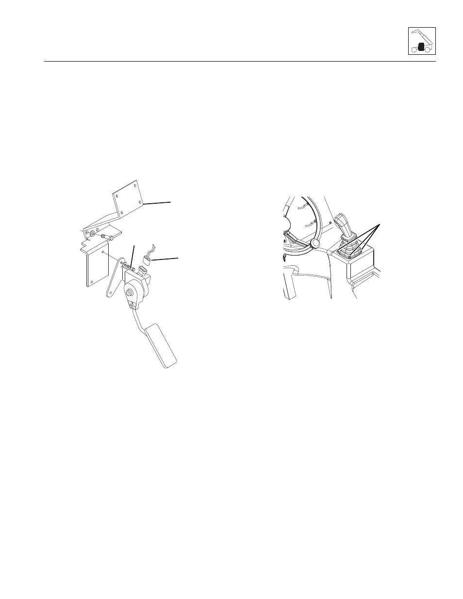
4.3.3
Throttle Pedal
a. Throttle Pedal Removal
1. Park machine on a firm, level surface, level machine,
fully retract boom, lower boom, place transmission
control lever in (N) NEUTRAL position, engage
parking brake and turn engine OFF.
2. Place a Do Not Operate Tag on both the ignition key
switch and steering wheel.
3. Properly disconnect the batteries.
4. Disconnect the electrical harness connector (4).
5. Remove the bolts (5) securing the throttle pedal to
the throttle pedal bracket (6).
6. Remove the throttle pedal assembly from the cab.
b. Throttle Pedal Installation
1. Position the throttle pedal in its mounting location
within the cab.
2. Secure throttle pedal into position with pivot pin.
3. Install throttle pedal ball joint to throttle pedal.
4. Properly connect the batteries.
5. Verify proper throttle pedal operation.
6. Close and secure the engine cover.
7. Remove the Do Not Operate Tags from both the
ignition key switch and the steering wheel.
4.3.4
Boom and Tilt Joystick Assembly
a. Joystick Assembly Removal
1. Park machine on a firm, level surface, level machine,
fully retract boom, lower boom, place transmission
control lever in (N) NEUTRAL position, engage
parking brake and turn engine OFF.
2. Place a Do Not Operate Tag on both the ignition key
switch and steering wheel.
3. Open engine cover. Allow the system fluids to cool.
4. Properly disconnect the batteries
5. Lift the joystick’s rubber sleeve, remove the bolts
securing the boom joystick to the cab (7).
6. Lift the joystick from its mounting position.
7. Label, disconnect and cap the hydraulic hoses
attached to boom joystick.
8. Disconnect the tilt function electronic connector.
9. Remove the joystick assembly.
MY0940
4
5
6
MY0950
7