2 lowering procedure, Warning – JLG G12-55A Service Manual User Manual
Page 66
Boom
3-30
G10-55A, G12-55A
Hoses:
• Two Hydraulic Hoses - Approximately 10 ft
(3,0 m) each, with a minimum I.D. of
0.375 in (9,5 mm) and a minimum rating of
4000 psi (275,8 bar).
G10-55A or G12-55A - Fittings:
• Two -12 ORFS Caps
• Two -12 ORFS Plugs
Adaptors:
• Two -12 ORFS 90° Adaptors
Note: The adaptor size may vary depending on the
hose ends of the auxiliary hydraulic power supply.
3.13.2
Lowering Procedure
a. Retract the boom as follows:
1. If equipped with Personal Work Platform, rescue
occupants prior to performing procedure.
2. Properly support the boom before attempting to
proceed with the emergency boom lowering
procedure.
3. Place a Do Not Operate Tag on both the ignition key
switch and steering wheel.
4. Properly support the boom as required.
5. Place a suitable receptacle under the main control
valve.
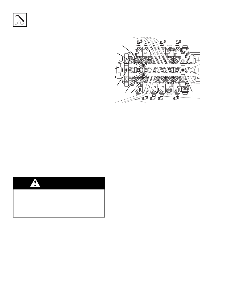
6. Remove the plastic cover from the top of the main
control valve.
7. Remove the brackets (5) that is attached to the steel
tubes supporting the plastic cover.
8. Loosen and remove any clamps securing the
extend/retract cylinder (1 & 2) and lift/lower cylinder
tubes (3 & 4) together and to the frame.
9. Disconnect the extend/retract cylinder tubes (1 & 2)
from the main control valve. Install plugs in tubes to
prevent fluid loss. Cap all fittings and openings to
keep dirt and debris from entering the hydraulic
system.
10. Using the hoses and fittings specified, connect the
hoses between the auxiliary hydraulic power supply
and the tubes removed from the main control valve
extend/retract section of the affected machine.
Retract tube (1) is the supply and extend tube (2) is
the return. Connect the hoses in the proper order to
ensure that the cylinder is retracted, not extended.
11. Remove the previously installed the boom support.
12. Use the auxiliary power supply to slowly retract the
extend/retract cylinder.
13. Properly support the boom as required.
14. Loosen and remove the jumper hoses, caps, plugs
and reconnect the extend/retract cylinder tubes.
Torque as required.
b. Lower the boom as follows:
1. Place a suitable receptacle under the main control
valve.
2. Disconnect the lift/lower cylinder tubes (3 & 4) from
the main control valve. Install plugs in tubes to
prevent fluid loss. Cap all fittings and openings to
keep dirt and debris from entering the hydraulic
system.
WARNING
Loss of hydraulic oil is limited to the amount trapped
within each tube/hose. Slowly loosen each hydraulic
tube fitting to release any possible hydraulic oil
pressure that may be trapped between the main
control valve and the counterbalance valve of the
extend/retract cylinder or the lift/lower cylinder.
MAL2690
1
4
G10-55A/G12-55A
5
5
2
3