8 quick switch assembly, 1 hydraulic quick switch removal, 2 hydraulic quick switch installation – JLG G12-55A Service Manual User Manual
Page 57: 3 manual quick switch removal, Quick switch assembly, Hydraulic quick switch removal, Hydraulic quick switch installation, Manual quick switch removal, Section, 8, “quick switch assembly
3-21
G10-55A, G12-55A
Boom
13. Cycle the auxiliary circuit and/or the tilt circuit,
verifying the auxiliary hoses and the tilt hoses are
NOT touching the bottom of the second boom
section and the proper slack, 4 in (101,6 mm) is
maintained.
14. Retract the boom and shut engine OFF.
15. Remove the Do Not Operate Tags from both the
ignition key switch and the steering wheel.
3.8
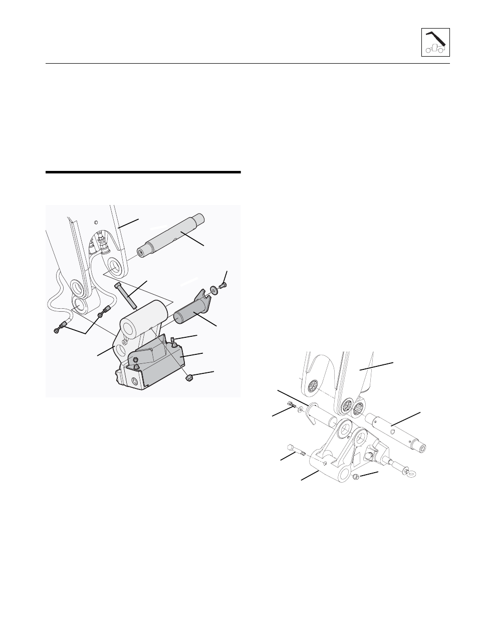
QUICK SWITCH ASSEMBLY
3.8.1
Hydraulic Quick Switch Removal
1. Remove hardware securing cylinder cover (15) and
remove cylinder cover.
2. Remove clamp hardware (16) securing cylinder
cover to hydraulic hoses (17).
3. Label and disconnect hydraulic hoses (17) attached
to quick switch assembly (10). Drain fluid into
suitable container.
4. Plug and cap the hose ends to prevent dirt and
debris from entering the hydraulic system.
5. Remove lock bolt (8) holding tilt cylinder rod end pin
(9) to quick switch assembly (10). Remove tilt
cylinder rod end pin.
6. Support quick switch assembly (10). Remove
capscrew (11) and locknut (12) securing head pin
(13) to boom head (14).
7. Remove the head pin (13) and the quick switch
assembly (10)
8. Inspect above pins for nicks or surface corrosion.
Use fine emery cloth to fix minor nicks or corrosion.
If damaged or if it cannot be repaired pin must
be replaced.
3.8.2
Hydraulic Quick Switch Installation
1. Assemble quick switch assembly (10) to boom head
(14). Line up quick switch between mounts on boom
head. The quick switch should be centered in the
boom head.
2. Coat head pin (13) with an anti-seize compound.
Insert head pin through quick switch and boom
head. Secure with capscrew (11) and locknut (12).
3. Align quick switch with tilt cylinder rod end and insert
tilt cylinder rod end pin (9). Align tilt cylinder rod end
pin and screw in locking bolt (8). Torque as required.
4. Uncap and install hydraulic hoses (17) to proper
fittings on quick switch assembly (10). torque
as required.
5. Secure hoses (17) to cylinder cover (15) with clamp
hardware (16).
6. Reinstall cylinder cover (15) with the hardware
removed earlier.
3.8.3
Manual Quick Switch Removal
1. Remove lock bolt (8) holding tilt cylinder pin (9) to
the quick switch assembly (10). Remove the tilt
cylinder pin.
2. Support quick switch assembly (10). Remove
capscrew (11) and locknut (12) securing head pin
(13) to boom head (14).
MY7390
13
12
10
11
8
9
14
15
16
17
MY5090
13
12
10
11
8
9
14