3 pressure specifications, In section 8.4.3, “pressure specifications, Section 8.4.3, “pressure specifications – JLG G12-55A Service Manual User Manual
Page 127
8-7
G10-55A, G12-55A
Hydraulic System
8.4.3
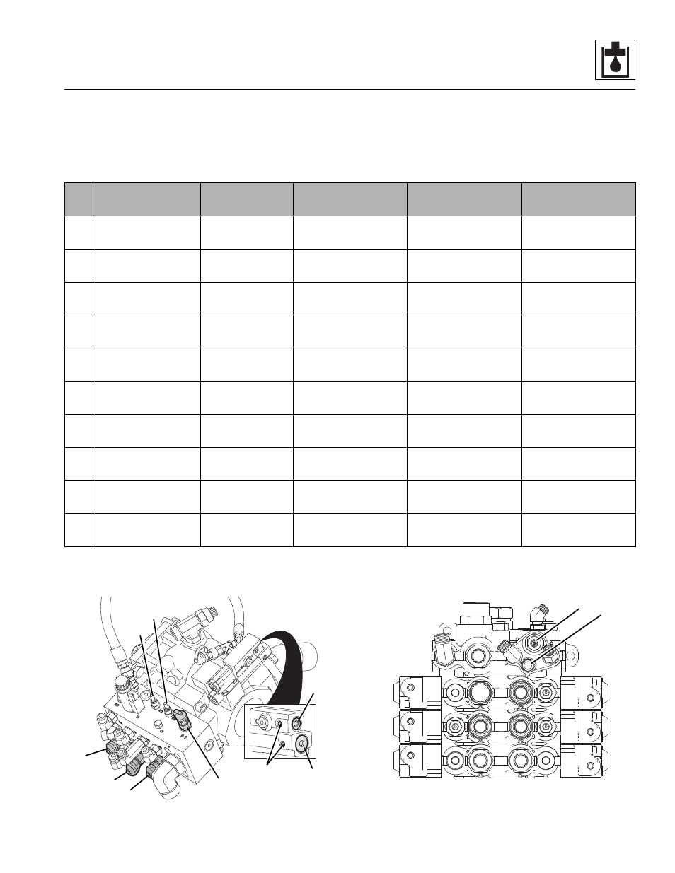
Pressure Specifications
Note: 1. All pressures must be checked in numerical order.
Note: 2. Connect gauge to P1 port, adjust Standby Pressure down to 300 psi (step 2). Adjust Main Compensator
Pressure to 3800 psi (step 3). Connect additional gauge to GLS (A) port, stall lift down, adjust Load Sense relief to the
setting noted below.
Note: Set Screws (7) must be loosened before adjusting Standby (1) or Main (2) ports. Tighten Set Screws when
adjustments are done.
Hydraulic Circuit
Test Port
Function Used to
Test
Adjustment
Location
Pressure Range
1
Load Sense Relief
GLS (A)
Bottom Lift Down
(See Note 2)
6
3250-3350 psi
(224-231 Bar)
2
Standby
P1 (B)
High Idle -
No Function
1
500-515 psi
(34-35 Bar)
3
Main
P1 (B)
High Idle -
Bottom Lift Down
2
3575-3675 psi
(246-253 Bar)
4
Pilot
JS (C)
High Idle - Bottom
Steering, Any Mode
4 (RV2)
500-550 psi
(34-38 Bar)
5
Service Brake
BV (D)
High Idle - Bottom
Steering, Any Mode
5 (RV1)
1050-1150 psi
(72-79 Bar)
6
Priority Load
Sense
GLS (A)
High Idle - Bottom
Steering, Any Mode
3
2375-2475 psi
(164-171 Bar)
7
Boom Extend
GLS (A)
High Idle - Bottom
Boom Extend
No Adjustment
3250-3350 psi
(224-231 Bar)
8
Boom Retract
GLS (A)
High Idle - Bottom
Boom Retract
No Adjustment
3250-3350 psi
(224-231 Bar)
9
Boom Lift
GLS (A)
High Idle - Bottom
Lift Up
No Adjustment
3250-3350 psi
(224-231 Bar)
10
Auxiliary Hydraulic
GLS (A)
High Idle - Bottom
Auxiliary Function
No Adjustment
3100-3300 psi
(214-227 Bar)
MY7070
2
5
1
4
B
C
D
A
HYDRAULIC
MANIFOLD
7
MY4361
6
3
MAIN CONTROL VALVE