Second, third and fourth boom section installation – JLG G12-55A Service Manual User Manual
Page 51
3-15
G10-55A, G12-55A
Boom
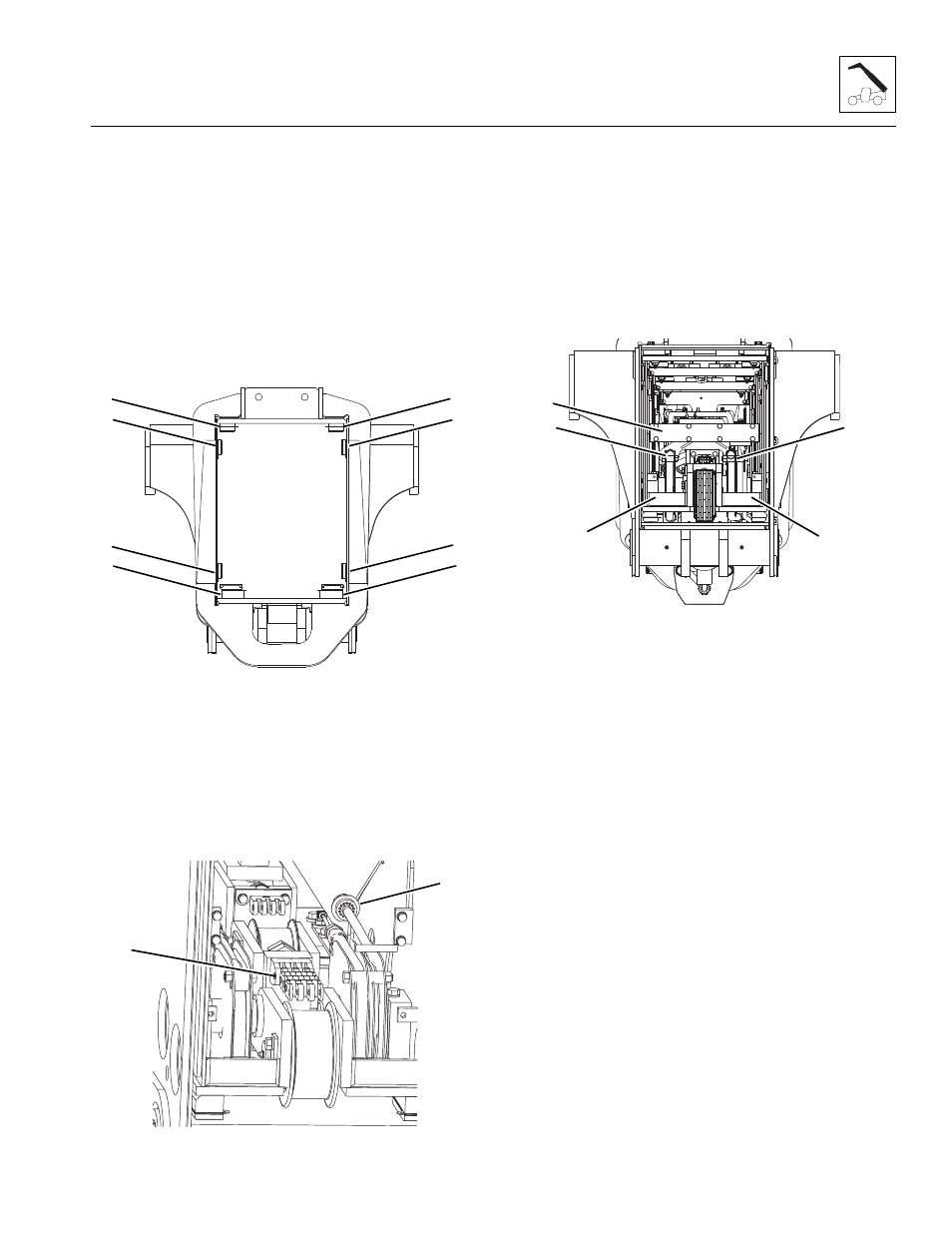
3.5.11
Second, Third and Fourth Boom
Section Installation
Note: Using a straight bar approximately 40 in
(1041 mm) long will aid in the installation of the wear
pads located on the inside front of each boom section.
1. Place one or two slings for better stability, around
second boom section and slowly insert second, third
and fourth boom sections into first boom section
being careful not to damage any surrounding
components and allowing sufficient room to install
wear pads at front of first boom section.
2. Install all wear pads, spacers and shims (1, 2 and 3)
at the front of the first boom section. Snug mounting
bolts. Shim as needed AFTER boom section is
installed. Refer to Section 3.9.2, “Wear Pad
Installation and Lubrication,” for detailed information.
3. Re-adjust the sling(s) and push the second, third
and fourth boom assembly the remainder of the way
into the first boom section.
4. Connect the rear retract chain (4) to the chain clevis
with the previously removed pin at the rear of the
third boom section. Secure the pin with the
previously removed snap rings.
5. Pull hose carrier from the rear as far as possible
to access the hydraulic and if equipped, the
electrical connections.
6. If equipped, connect the electrical cable (5) to the
fitting on the hose carrier.
7. Remove any caps and plugs from the tilt and
auxiliary hoses at the rear of the boom assembly.
Connect and tighten the tilt (6) and auxiliary hoses
(7) to their proper fitting locations on the hose
carrier. Torque as required.
8. Install hose carrier bracket (8) at rear of third boom
section and the hose carrier. Torque mounting bolts
as required.
9. Install both hose sheave covers (9).Torque mounting
bolts as required.
MY4140
3
2
2
1
3
2
2
1
MY3590
4
5
MY3420
6
7
8
9
9