6 air cleaner assembly, 1 air cleaner assembly removal—uls, 2 air cleaner assembly installation —uls – JLG G12-55A Service Manual User Manual
Page 116: Air cleaner assembly, Air cleaner assembly removal—uls, Air cleaner assembly installation —uls, Warning
Engine
7-12
G10-55A, G12-55A
7.6
AIR CLEANER ASSEMBLY
Note: Refer to the appropriate Operation & Safety
Manual for your machine for the correct element change
procedure.
7.6.1
Air Cleaner Assembly Removal—ULS
1. Park machine on a firm, level surface, level machine,
fully retract boom, lower boom, place transmission
control lever in (N) NEUTRAL position, engage
parking brake, and shut engine OFF.
2. Place a Do Not Operate Tag on both the ignition key
switch and steering wheel.
3. Open engine cover. Allow system fluids to cool.
4. Properly disconnect batteries.
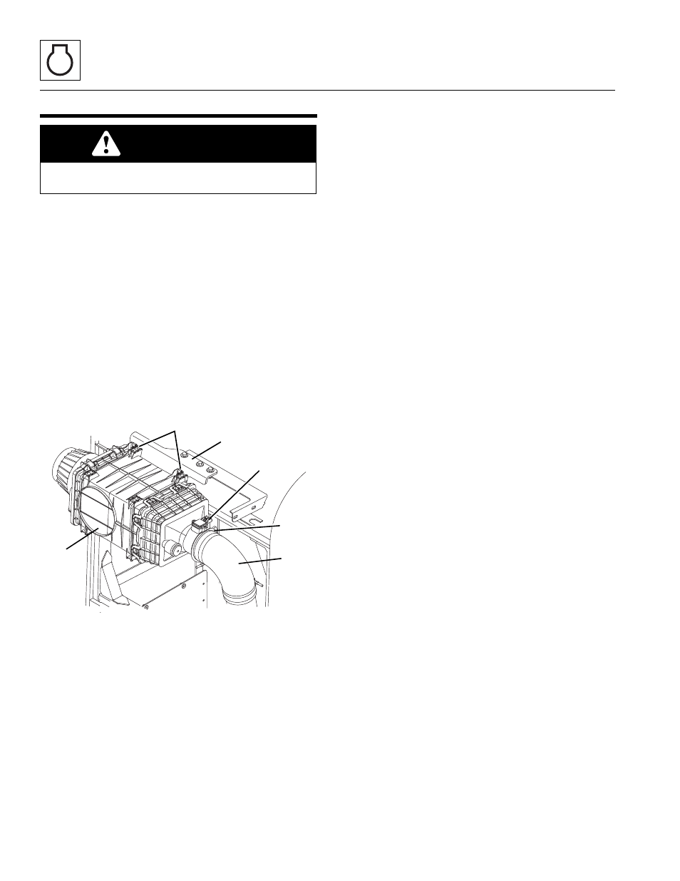
5. Loosen clamp (1) securing air intake elbow (2) to the
air cleaner assembly (3). Pull air intake elbow off air
the cleaner.
6. Disconnect sensor (4).
7. Remove the screws securing mounting bracket (6) to
the cab.
8. Remove capscrews and nuts (5) securing air cleaner
assembly (3) to mounting bracket (6). Remove air
cleaner assembly.
7.6.2
Air Cleaner Assembly Installation
—ULS
Note: Apply Loctite
®
242™
to the capscrew threads
before installation.
1. Install the air cleaner assembly (3) to mounting
bracket (6) with previously removed hardware (5).
2. Install mounting bracket onto cab with previously
removed hardware.
3. Place loosened clamp (1) over air intake elbow (2)
and install elbow on air cleaner assembly.
4. Adjust and tighten the clamp.
5. Connect sensor (4).
6. Properly connect the batteries.
7. Close and secure the engine cover.
8. Remove Do Not Operate Tags from both ignition key
switch and steering wheel.
WARNING
NEVER run the engine with only the inner safety
element installed.
MY7040
5
4
2
1
3
6
IF EQUIPPED FOR ULS