10 boom extend/retract chain removal/installation, 1 boom retract chain removal, Boom extend/retract chain removal/installation – JLG G12-55A Service Manual User Manual
Page 59
3-23
G10-55A, G12-55A
Boom
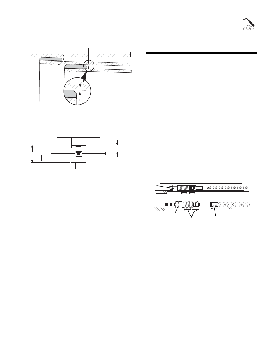
• Maintain a total boom section clearance (5) of
0.070–0.130 in (1,78–3,30 mm) both the horizontal
and vertical directions.
• The length of the wear pad bolt depends on the
number of shims, spacers and washers being used.
• The thickness of each threaded wear pad insert is
0.312 in (7,92 mm) (A).
• Bolt length should be determined by measuring the
distance from face of insert to face of boom (B)
including any spacer, shim(s) and washer(s).
• Bolt thread engagement in the wear pad insert
should be 0.275 ± 0.040 in (6,98 ± 1,0 mm).
• One or two hardened washers are to be used on
each wear pad bolt except where noted otherwise.
DO NOT use more than two hardened washers.
• Use only one hardened washer if mounting bolts
are recessed.
• Wear Pad Bolt Torque:
3/8 - 24 Bolt, 32–37 lb-ft (43–50 Nm)
3/8 - 24 Hollow Bolt, 15–17 lb-ft (20–23 Nm)
1/2 - 20 Bolt, 76–86 lb-ft (103 - 116 Nm)
1/2 - 20 Hollow Bolt, 45–50 lb-ft (61–68 Nm)
• Torque wear pad bolts after shimming is completed.
• Lubricate the face and pockets of each wear pad
after being installed.
Boom Section Wear Pad Pathway Lubrication:
• Clean and lightly grease all wear pad pathways with
Mystik Tetrimoly grease.
• Clean and lightly grease the hose carrier guide bar
pathways with Mystik Tetrimoly grease.
3.10
BOOM EXTEND/RETRACT CHAIN
REMOVAL/INSTALLATION
3.10.1
Boom Retract Chain Removal
The following section explains the removal of the retract
chains without removing the boom assemblies.
Note: The retract chain on the bottom of the boom must
be removed to gain access to the inner retract chain.
To remove retract chain from third to first boom sections:
1. Park the machine on level ground. Place the
transmission control lever in (N) NEUTRAL, engage
the parking brake switch, level the boom and shut
the engine OFF.
2. Place a Do Not Operate Tag on both the ignition key
switch and the steering wheel.
3. Properly disconnect the batteries.
4. Attach a suitable sling to the extend/retract cylinder.
Remove the extend/retract cylinder support.
5. Remove rod end pin and lower cylinder onto frame
rails. Lowering extend/retract cylinder will allow
access to chains.
6. Remove tension from the chain by backing off the
jam nut and adjusting nut (1).
7. Remove four bolts (2) from chain adjustment block.
8. Remove chain from clevis (3) at block.
9. Install a nylon tie wrap through holes of removed
chain, making a loop with a tie wrap and tie a rope to
the loop.
10. At the rear of the boom, pull the chain to the rear to
allow slack for removal.
11. Remove the chain from the clevis and drop it free
from the boom.
12. Holding a rope at front adjustment block, carefully
pull chain out through back of boom.
13. Untie the rope and leave it in place for reinstallation
of the chain.
MY5510
5
5
MY3620
A
B
MX0510
1
2
3
4