JLG G12-55A Service Manual User Manual
Page 50
Boom
3-14
G10-55A, G12-55A
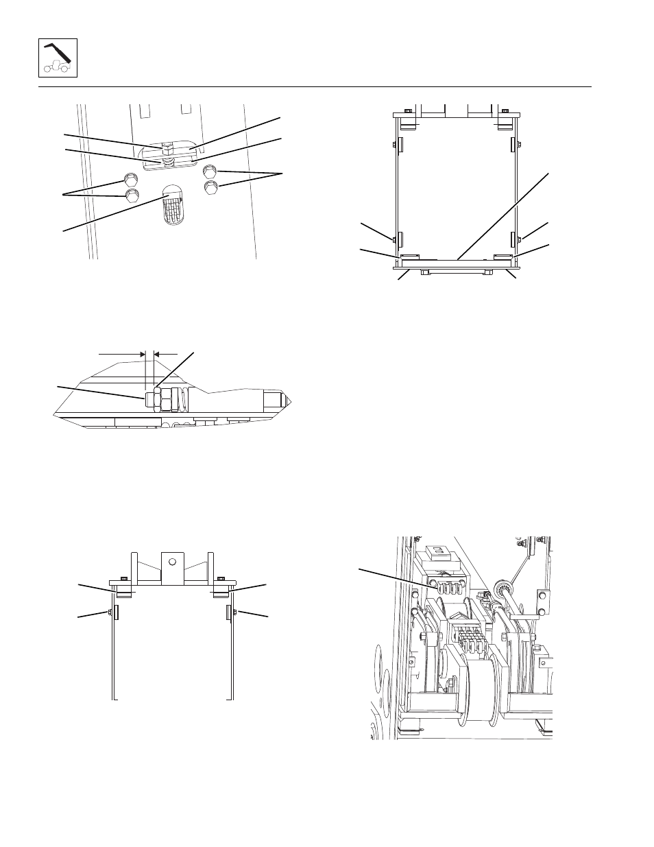
2. Install adjusting block (17) using existing hardware
(18). Torque as required.
3. Install chain and clevis (19), spring (20), spring stop
(21), adjusting nut and lock nut (22).
4. Allow 0.50 in (1,27 mm) (A) between the end of the
clevis (23) and the face of the lock nut (24). Torque
lock nut to 100 lb-ft (135 Nm).
5. Properly connect the batteries.
6. Retract the second boom section pulling both retract
chains at the same time.
7. Install the wear pad, support plates and spacers (25)
with existing hardware at the inside top front of the
second boom section. Snug mounting bolts. Shim as
needed AFTER boom section is installed. Refer to
Section 3.9.2, “Wear Pad Installation and
Lubrication,” for detailed information.
.
8. Install the wear pad support plate (27) with existing
hardware at inside front of second boom section.
Note: Longer bolts (30) may be required to fully engage
threaded inserts in the wear pads without allowing bolts
to protrude past the chamfer on the wear pads. Refer to
Section 3.9.2, “Wear Pad Installation and Lubrication.”
9. Install wear pads, spacers and shims on each side
and bottom (26, 28 and 29) at front of second boom
section. Snug mounting bolts. Shim as needed
AFTER boom section is installed. Refer to Section
3.9.2, “Wear Pad Installation and Lubrication,” for
detailed information.
10. Manually retract the boom sections as required to
connect the retract chains.
11. Install bracket and clevis assembly (31) at rear of
fourth boom section. Torque mounting bolts.
MY3540
18
17
19
18
21
22
20
A
MY3650
24
23
25
25
26
26
MY3450
28
29
30
30
29
28
27
MY3590
31