7 engine replacement, 1 engine removal, Engine replacement – JLG G12-55A Service Manual User Manual
Page 118: Section 7.7.1, “engine removal, Engine removal
Engine
7-14
G10-55A, G12-55A
7.7
ENGINE REPLACEMENT
7.7.1
Engine Removal
Note: The radiator and oil cooler must be removed from
the machine before engine removal. Refer to
7.2, “Engine Cooling System.” Several additional
components must be removed before engine removal.
They will be addressed in the following procedures.
1. Park machine on a firm, level surface, level machine,
fully retract boom, lower boom, place transmission
control lever in (N) NEUTRAL position, engage
parking brake, and shut engine OFF.
2. Place a Do Not Operate Tag on both the ignition key
switch and steering wheel.
3. Open engine cover. Allow system fluids to cool.
4. Properly disconnect and remove batteries. Remove
engine cover. Mark position of cover to help with
cover adjustment when being reinstalled.
5. Remove the oil pan cover underneath the
engine compartment.
6. Drain and remove the radiator assembly. Refer to
Section 7.2.3, “Radiator/Oil Cooler and
Replacement.”
7. Remove the heater hoses attached to the engine
(if equipped).
Note: Engine harness is routed and attached to engine
using hold-down clamps and plastic wire ties at various
places on engine. Before removing engine, ensure that
harness has been completely separated (disconnected)
from engine. Move harness clear of engine, and with
help of an observer, ensure that engine clears harness
during removal.
8. Label and disconnect all electrical wire connections
on the engine.
9. Label and disconnect all electrical wire connections
on the Power Distribution bracket.
10. Remove the Power Distribution bracket.
11. Disconnect and cap fuel inlet line at fuel filter head.
12. Disconnect and cap the fuel return line from the fuel
filter head.
13. Remove exhaust pipe from the exhaust manifold.
Refer to Section 7.5.1, “Exhaust System Removal—
ULS.”
14. Loosen clamps on sleeve reducer at engine and on
air suction pipe.
15. Remove air cleaner tube from turbo charger.
16. Remove access plug from bottom of engine bell
housing. This will allow access to remove bolts
holding the torque convertor diaphragm to the
engine flywheel.
17. Turn engine over slowly by hand and align each of
four torque convertor diaphragm bolts to be
accessed. Remove them one at a time.
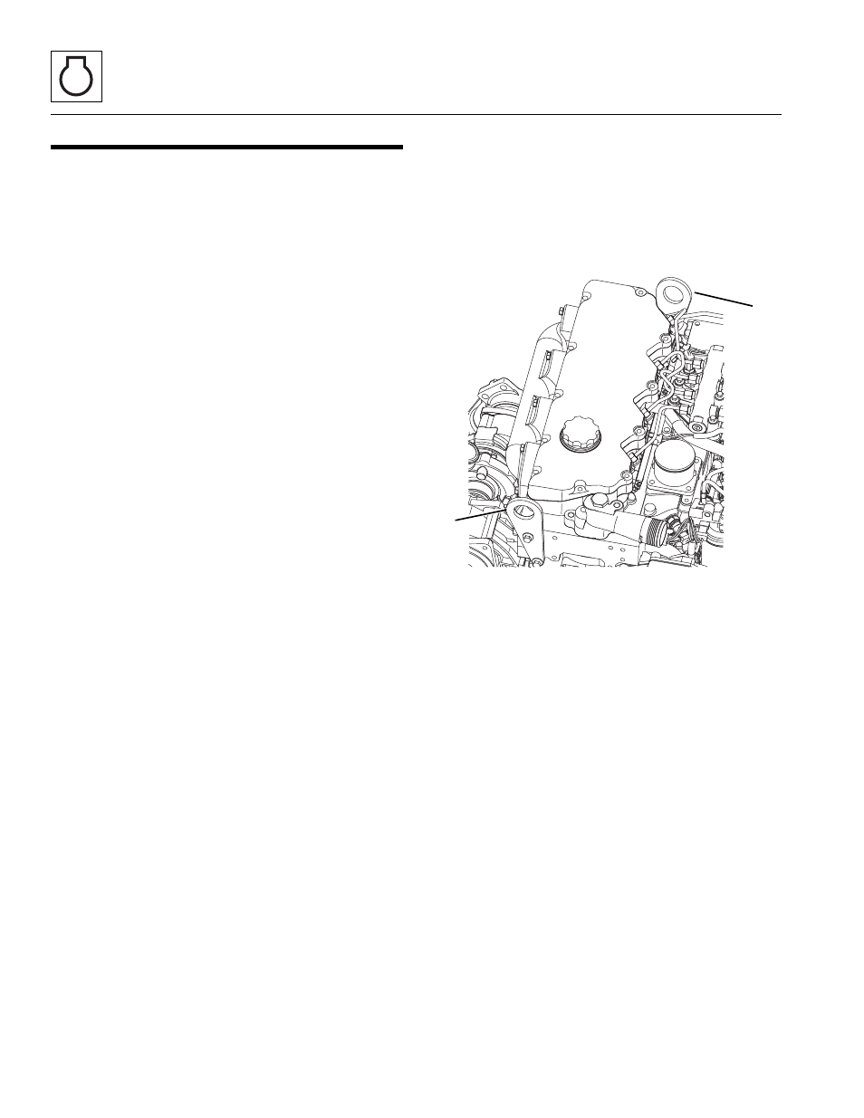
18. Secure the engine with a lifting strap or chain from
the appropriate lifting points (1). Use a suitable hoist
or overhead crane.
19. Place a support or jack under transmission to hold
transmission in place while engine is being removed.
20. Remove bolts and washer securing engine mounts.
21. Remove bolts holding transmission to engine.
Slightly lift and pull engine out of machine. Have an
assistant ensure that engine clears all frame
components during removal.
22. Place engine on a flat, level surface.
MY4270
1
1