8 hydraulic cylinders, 1 general cylinder removal instructions, Hydraulic cylinders – JLG G12-55A Service Manual User Manual
Page 138: R to section, 8, “hydraulic cylinders, Tosection, Section 8.8, “hydraulic cylinders, General cylinder removal instructions, Warning
Hydraulic System
8-18
G10-55A, G12-55A
Note: Check for leaks and repair as required before
continuing. Add hydraulic fluid to the reservoir as
needed.
7. Wipe up any hydraulic fluid spillage in, on, near and
around the machine, work area and tools.
8. Close and secure the engine cover.
9. Remove the Do Not Operate Tags from both the
ignition key switch and the steering wheel.
d. Steering Test
Refer to Section 8.4.1, “Hydraulic Pressures.”
1. Conduct a pressure check of steering
hydraulic circuit.
2. Check each steering mode for proper function.
8.8
HYDRAULIC CYLINDERS
8.8.1
General Cylinder Removal Instructions
1. Remove any attachment from machine. Park
machine on a firm level surface and fully retract
boom. Allow sufficient work space around hydraulic
cylinder being removed. Support boom if lift/lower
cylinder is being removed. Place transmission
control lever in (N) NEUTRAL, engage park brake,
shut engine OFF and chock wheels.
2. Place a Do Not Operate Tag on both the ignition key
switch and the steering wheel.
3. Open engine cover. Allow system fluids to cool.
4. Properly disconnect the batteries.
5. Label, disconnect and cap or plug hydraulic hoses in
relation to the cylinder.
6. Attach a suitable sling to an appropriate lifting device
and to the cylinder. Make sure the device used can
actually support the cylinder.
7. Remove the lock bolt and/or any retaining clips
securing the cylinder pins. Remove the cylinder pins.
8. Remove the cylinder.
9. Wipe up any hydraulic fluid spillage in, on, near and
around the machine, work area and tools.
a. General Cylinder Disassembly
1. Clean the cylinder with a suitable cleaner before
disassembly. Remove all dirt, debris and grease
from the cylinder.
2. Clamp barrel end of cylinder in a soft-jawed vise or
other acceptable holding equipment if possible.
Note: Avoid using excessive force when clamping the
cylinder in a vise. Apply only enough force to hold the
cylinder securely. Excessive force can damage the
cylinder tube.
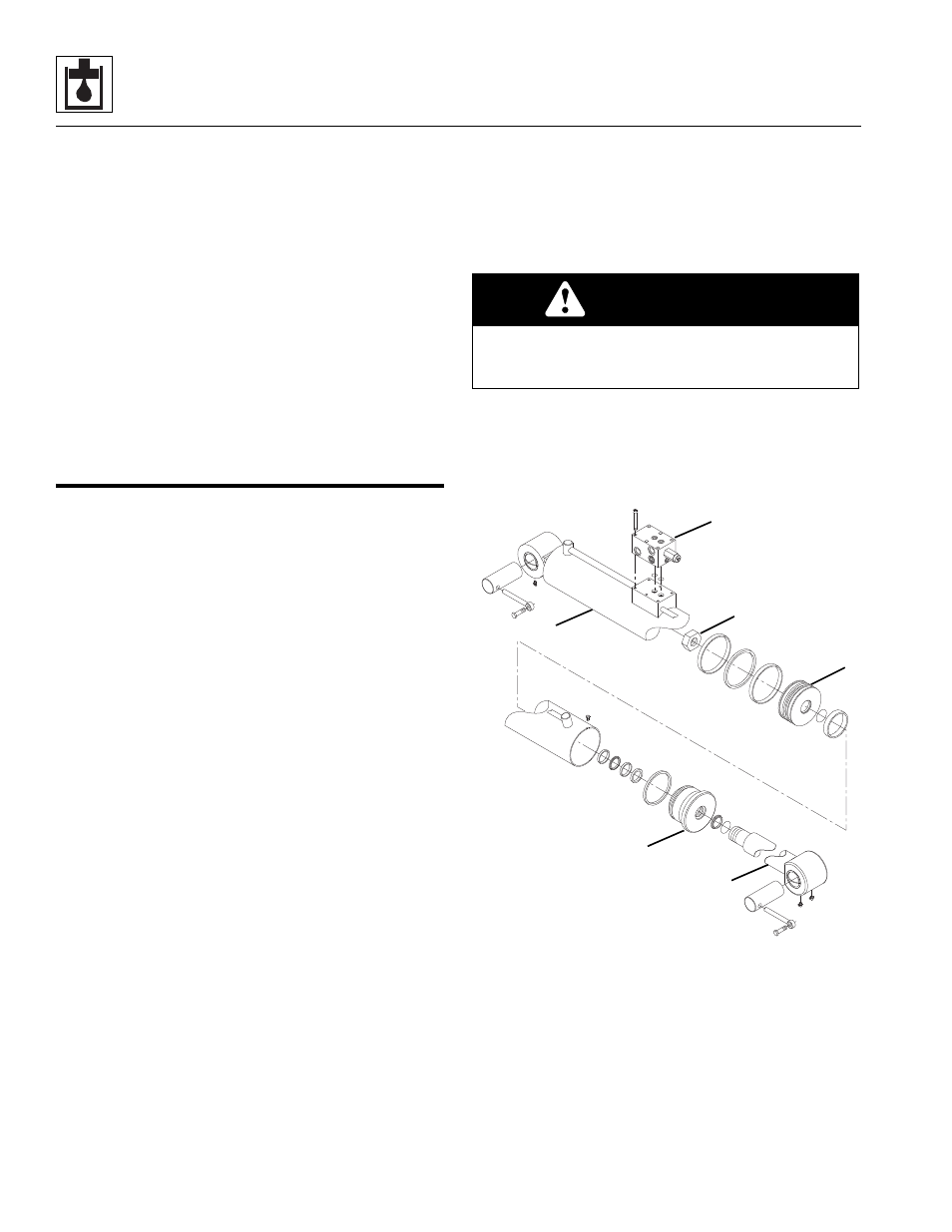
3. If applicable, remove the counterbalance valve (1)
from the side of the cylinder barrel (2).
Note: DO NOT tamper with or attempt to adjust the
counterbalance valve cartridge. If adjustment or
replacement is necessary, replace the counterbalance
valve with a new part.
4. Extend the rod (3) as required to allow access to the
base of the cylinder.
WARNING
Significant pressure may be trapped inside the cylinder.
Exercise caution when removing a counterbalance valve
or a pilot-operated check valve from a cylinder.
MY4300
1
2
3
4
5
6