4 boom hose take-up adjustment, 5 boom hose adjustment, Boom hose adjustment – JLG G12-55A Service Manual User Manual
Page 56
Boom
3-20
G10-55A, G12-55A
11. Uncap and reconnect the previously labeled tilt and
auxiliary hydraulic hoses to the proper fittings at the
front of the fourth boom section.
12. If equipped, reconnect any electrical connections at
the front and rear of the boom assembly.
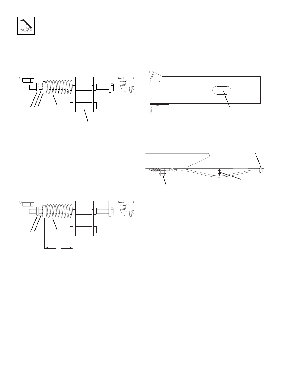
13. Install the boom hose take-up compression spring
(4) on each hose take-up bracket (5) at the bottom of
the first boom section. Install the washer (6),
adjusting nut (7) and jam nut (8).
14. Properly connect the battery.
15. Remove the Do Not Operate Tags from both the
ignition key switch and the steering wheel. Refer to
Section 3.7.4, “Boom Hose Take-up Adjustment,” for
detailed adjustment procedure.
3.7.4
Boom Hose Take-up Adjustment
1. Tighten the adjusting nut (7) to compress the hose
take-up compression spring (4) to measure 2.875-
3.187 in (73-81 mm)(9). Refer to Section 3.7.5,
“Boom Hose Adjustment,” if required.
2. Torque the jam nut (8) against the adjusting nut (7)
to 100 ft-lb (135,5 Nm).
3.7.5
Boom Hose Adjustment
1. Park the machine on a hard, level surface, level the
machine, fully extend the boom, lower the boom
head to the ground, place the transmission control
lever in (N) NEUTRAL, engage the park brake and
shut the engine OFF.
2. Place a Do Not Operate Tag on both the ignition key
switch and the steering wheel.
3. Verify any trapped hydraulic pressure in the auxiliary
circuit and the tilt circuit is relieved.
4. Open the engine cover. Allow the system fluids to
cool.
5. Verify the auxiliary hoses and/or tilt hoses are NOT
touching the bottom of the second boom section by
viewing the auxiliary hoses and/or tilt hoses through
the access hole (10) in each side of the second
boom section.
6. Verify that 4 in (101,6 mm) of slack (11) is present
between the hose take-up bracket (5) and the first
hose clamp (12).
7. Verify the hose take-up bracket (5) is not bent and is
at an 85° angle to the hose.
Note: Replace both auxiliary hoses and/or tilt hoses if
the hoses are touching the bottom of the second boom
section AND 4 in (101,6 mm) of slack is present between
the hose take-up bracket and the first hose clamp.
8. Refer to Section 3.7.4, “Boom Hose Take-up
Adjustment,” for boom hose take-up adjustment.
9. Measure the slack (11) at the lowest point between
the hose take-up bracket (5) and the first hose clamp
(12). The 4 in (101,6 mm) measurement is from the
bottom of the first boom section to the top of the
hose.
10. If necessary, loosen the hose clamp (12), pull the
auxiliary hoses and/or the tilt hoses, tighten the hose
clamp for additional clearance.
11. Replace the auxiliary hoses and/or the tilt hoses if
the proper slack, 4 in (101,6 mm)(11) cannot be
achieved.
12. Start the machine, raise the boom to level, cycle the
extend/retract cylinder, fully extend the boom.
MY9310
4
5
8 7 6
MY2691
9
8 7
4
MY4480
10
MY4470
12
5
11