2 tilt circuit port relief adjustment, Tilt circuit port relief adjustment – JLG G12-55A Service Manual User Manual
Page 125
8-5
G10-55A, G12-55A
Hydraulic System
3. Tighten jam nut and recheck pressure at full throttle.
If reading is within specification, shut machine off,
install safety cap and remove gauge from test port.
4. If proper pressure cannot be set, use accompanying
hydraulic schematic and/or electrical schematic to
help troubleshoot and correct problem.
8.4.2
Tilt Circuit Port Relief Adjustment
The following procedure is specific to tilt circuit only and
should be performed and verified if main and/or load
sense circuits pressures are in question.
1. Remove any attachment from the quick coupler
assembly. Refer to the Operation & Maintenance
Manual for attachment removal information.
2. Raise boom for access to compensation cylinder.
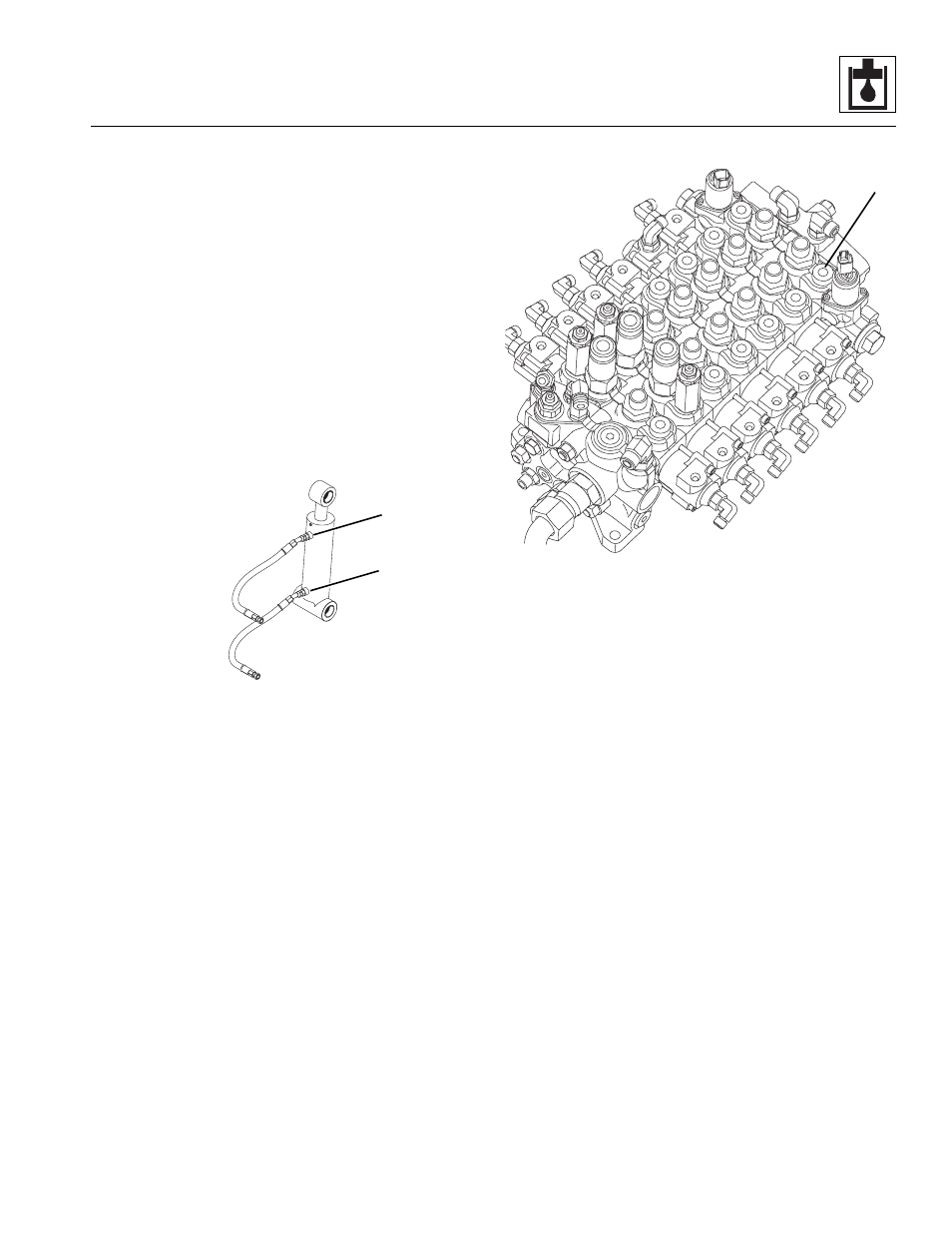
3. Slowly loosen and remove the retract (1) hose from
the compensation cylinder.
4. Install a tee fitting to retract (1) port of compensation
cylinder. Reconnect previously removed retract (1)
hose to tee fitting.
5. Slowly loosen and remove extend (2) hose from
compensation cylinder.
6. Install a tee fitting to extend (2) port of compensation
cylinder. Reconnect previously removed extend (2)
hose to tee fitting and cap open port.
7. Install a digital or a 5000 psi (345 bar) gauge to
retract (1) port tee fitting on compensation cylinder.
8. Start machine and warm the hydraulic system to
operating temperature.
9. Tilt forks down to allow tilt cylinder to fully retract.
10. Monitor gauge and slowly raise boom. The gauge
should read 4100 psi (282 bar).
11. If pressure is correct, proceed to step 14.
12. Relief on (A) port of main control valve is
non-adjustable and must be replaced. Replace
and repeat steps 9 and 10.
13. Verify pressure is correct.
14. Shut engine OFF.
15. Remove digital or 5000 psi (345 bar) gauge from
retract (1) port fitting on compensation cylinder and
cap open port.
16. Remove cap and install a digital or a 5000 psi (345
bar) gauge to extend (2) port tee fitting on the
compensation cylinder.
17. Start machine and if needed, warm hydraulic system
to operating temperature.
18. Tilt forks up to allow tilt cylinder to fully extend.
19. Monitor gauge and slowly lower boom. The gauge
should read 4100 psi (282 bar).
20. If pressure is correct, proceed to step 23.
MY5520
2
1
MY7060
FRONT OF MACHINE
A