JLG E300 Service Manual User Manual
Page 76
SECTION 3 - CHASSIS & TURNTABLE
3-42
– JLG Lift –
3121253
NOTE: It may be necessary to turn one alignment stud out
of the housing (18) temporarily to assemble rotor set
(8) or manifold (7) over the drive link.
NOTE: If necessary, go to the appropriate, "Rotor Set Com-
ponent Assembly Procedure."
NOTE: The rotor set rotor counterbore side must be down
against wear plate for drive link clearance and to
maintain the original rotor-drive link spline contact. A
rotor set without a counterbore and that was not
etched before disassembly can be reinstalled using
the drive link spline pattern on the rotor splines if
apparent, to determine which side was down. The
rotor set seal ring groove faces toward the wear plate
(9).
14. Apply clean grease to a new seal ring (4) and
assemble it in the seal ring groove in the rotor set
contact side of manifold (7).
NOTE: The manifold (7) is made up of several plates
bonded together permanently to form an integral
component. The manifold surface that must contact
the rotor set has it’s series of irregular shaped cavi-
ties on the largest circumference or circle around the
inside diameter. The polished impression left on the
manifold by the rotor set is another indication of
which surface must contact the rotor set.
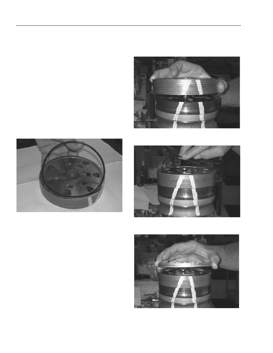
15. Assemble the manifold (7) over the alignment studs
and drive link (10) and onto the rotor set. Be sure the
correct manifold surface is against the rotor set.
16. Apply grease to a new seal ring (4) and insert it in
the seal ring groove exposed on the manifold.
17. Assemble the commutator ring (6) over alignment
studs onto the manifold.
18. Assemble a new seal ring (3) flat side up, into com-
mutator (5) and assemble commutator over the end