Clamp block installation -6 – JLG E300 Service Manual User Manual
Page 104
SECTION 4 - BOOM & PLATFORM
4-6
– JLG Lift –
3121253
13. Using JLG P/N 0100011 thread locking compound
or equivalent, install the retaining bolt, keeper, and
pin that secures the level cylinder to the jib. Torque
the retaining bolt to 35 ft.lbs. (48 Nm).
14. Route the hydraulic hoses on top of the jib and
install the hose cover.
15. Connect all hydraulic lines running to the plaform
rotator, jib rotator (if equipped), and jib cylinder as
tagged during removal.
16. Connect all electrical lines running to the platform as
tagged during removal.
17. Using all safety precautions, operate machine sys-
tems and extend and retract boom for four or five
cycles, checking for proper operation.
18. Shut down the machine and check for leakage.
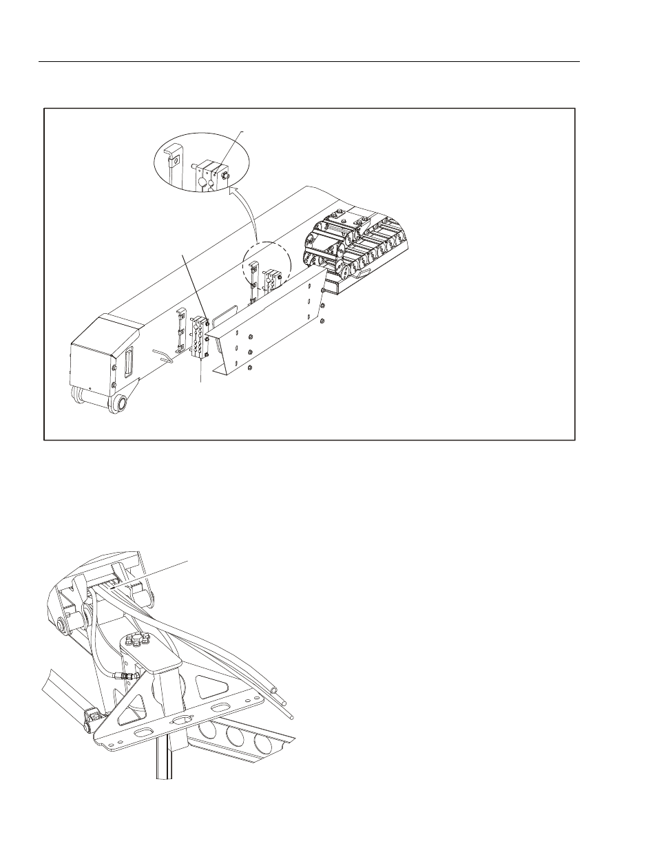
PUSH NUT
CLAMP BLOCK
CLAMP BLOCK INSTALLATION INSTRUCTIONS
1. TO PROVIDE ORIENTATION OF THREADED STUDS,
LOOSELY INSTALL THREADED STUD INTO
CLIP NUT UNTIL FIRST SECTION OF CLAMP
BLOCK IS INSTALLED
2. TORQUE THREADED STUD TO 10 FT.LB. (13.5 Nm)
3. CONTINUE INSTALLING HOSES, CABLES, AND CLAMP
BLOCK SECTIONS
4. INSTALL PUSH NUTS ONTO THREADED STUDS
TO HOLD CLAMP BLOCKS IN POSITION WHILE
COVER IS INSTALLED.
ORIENT CLAMP BLOCK SECTIONS
USING ALIGNMENT HOLES AS SHOWN
Figure 4-4. Clamp Block Installation
ROUTE HOSES AND CABLES
THROUGH CHANNELS ON JIB
AS SHOWN