Figure 13: narrowband o2 sensor connection – AEM 30-1913 Universal Fuel Ignition Controller 6 Channel User Manual
Page 8
Page 8
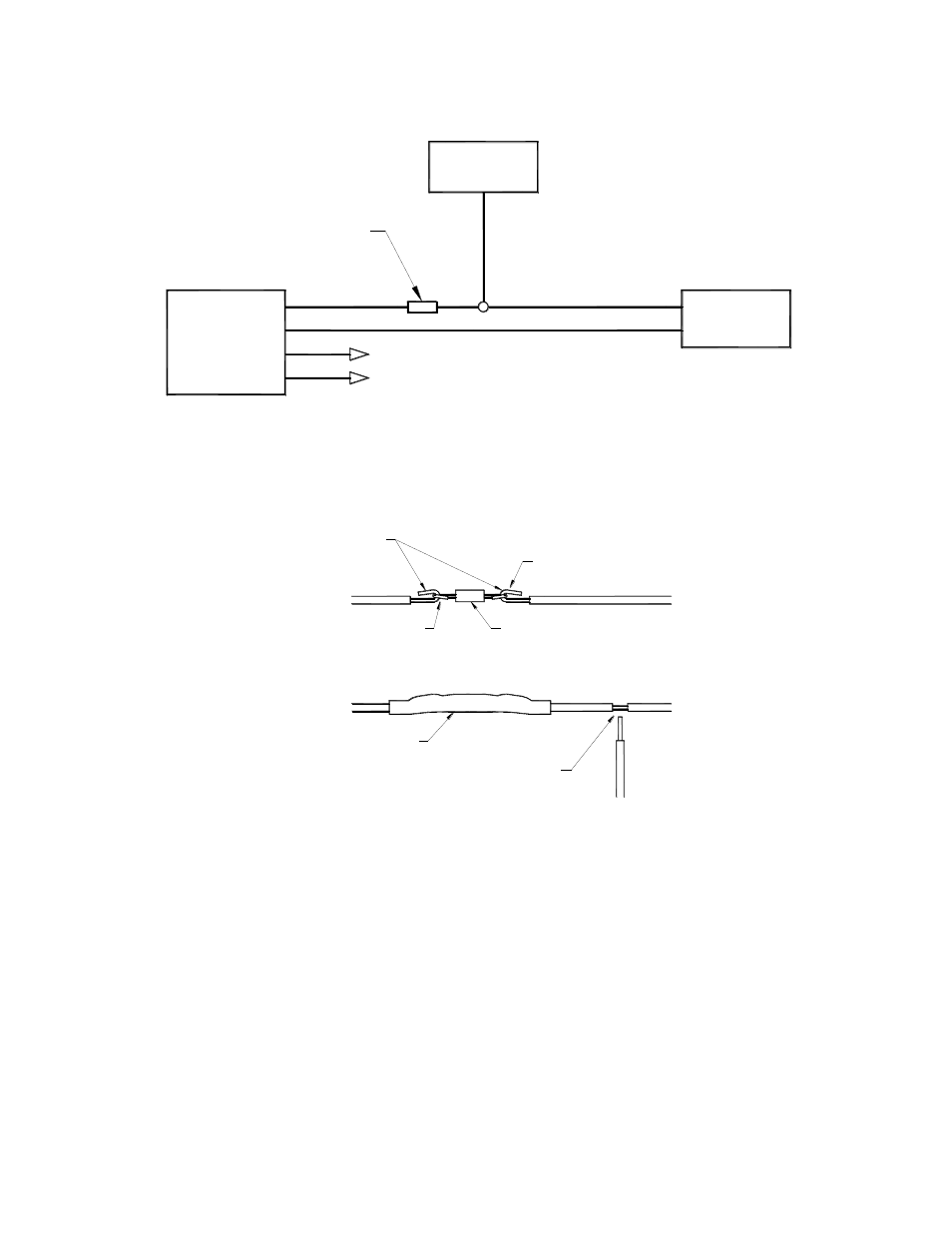
Do you want to modify the Oxygen(O2)/UEGO sensor signals?
If not, the
“O2” sensor wires can be eliminated. If so, connect the sensors as
shown below in Figures 13, 14, 15 and/or 16.
TO FACTORY HARNESS
FIC
SEE RESISTOR DETAIL
POWER
SIGNAL GND
HEATER
SIGNAL
SENSOR
O21
+
ECU
Figure 13: Narrowband O2 sensor connection
TAP CONNECTION MUST BE
ON ECU SIDE OF RESISTOR
1K 1/4W RESISTOR
TO NARROW BAND O2 SENSOR
AROUND RESISTOR LEADS
TO NARROW BAND O2 SENSOR
APPLY SHRINK TUBING
AFTER SOLDERING
WRAP BARE WIRES
SOLDER
TO F/IC
SOLDER
TO ECU
TO ECU
Figure 14: 1K resistor detail for narrowband O2 sensor
This manual is related to the following products: