AEM 30-1913 Universal Fuel Ignition Controller 6 Channel User Manual
Page 27
Page 27
The RPM calibration is performed by running the engine at the RPM shown in the RPM
box, as directed by the on-screen instructions. The RPM in the window can be changed
if desired. Click Auto in the RPM section and follow the on-screen instructions. The TPS
calibration is a two-point calibration, one at 0% throttle and one at 100% throttle. Click
Auto in the TPS section and follow the on-screen instructions to calibrate the TPS.
(Note: For drive by wire applications, the engine may need to be running in order to
open the throttle plate to 100%. Quickly blip the throttle to 100% and click the ok
button.) Always verify the TPS and RPM calibrations after uploading a file from a
different source. (Note: The TPS and RPM calibration settings are stored in the
calibration file.)
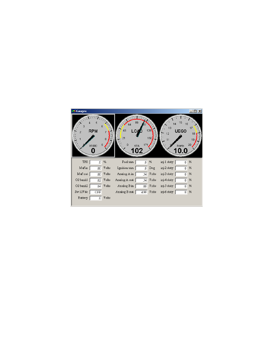
Gauges Window:
To aid in tuning, the F/IC software has a Gauges window that gives real-time
reference to the engine
’s operating conditions. See Figure 41.
Figure 41: F/IC gauges window
The Gauges window contains a user configurable Tachometer, Pressure (Load) gauge,
and an Auxiliary gauge (UEGO in Figure 41), along with real-time displays of TPS, MAF
volts, O2 volts, Switched 12V
DC
status, Battery volts, Fuel Trim, Analog A, Analog B,
and Ignition trim. Each gauge has an overload alarm, yellow highlight, red highlight, and
full-scale settings. To configure a gauge, place the cursor over the gauge and double
click the left mouse button. A pink needle will appear. Move the cursor over the needle,
hold the left mouse button and drag the needle to the desired value. Double clicking on
the left mouse button will move the gauge to the next configurable setting.
Auxiliary Gauge (UEGO)
The Auxiliary gauge (UEGO) is a user configurable display based on a 0-5 volt
analog input. The Auxiliary gauge was specifically created so the F/IC can display and
log AFR based on the analog output from the AEM UEGO gauge or controller.
However, since the gauge is user configurable, it will work with any 0-5 volt analog
signal. To configure the auxiliary gauge, open the
“Auxiliary gauge setup” window by
clicking on Setup>Aux Gauge. See Figure 42.