AEM 30-1913 Universal Fuel Ignition Controller 6 Channel User Manual
Page 22
Page 22
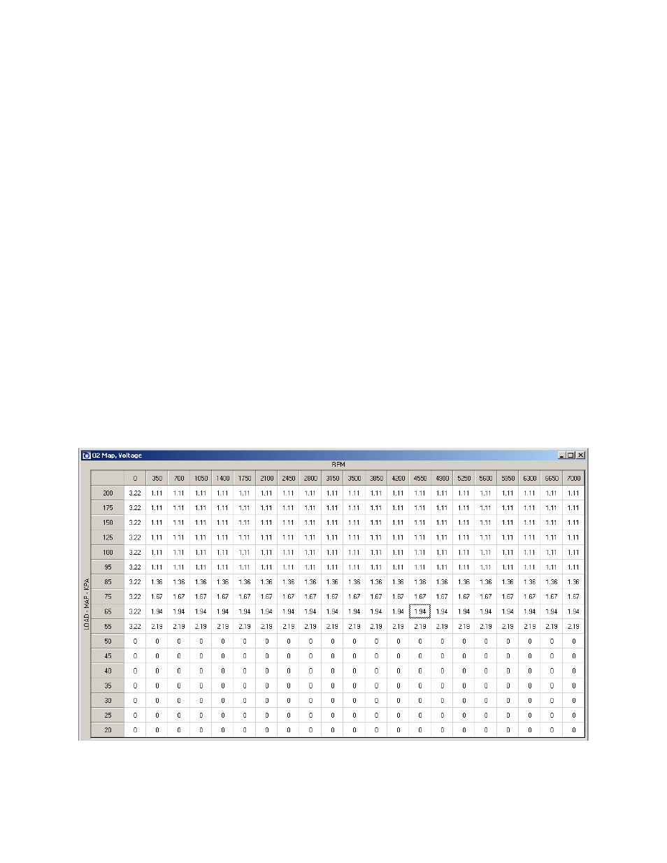
O2 Map (See Figure 35)
At times, such as a track day or race event, you may desire to alter the closed-
loop air-fuel ratio (AFR) of the factory ECU to achieve better engine performance. This
can be done using the O2 functionality of the F/IC. By outputting a different signal, the
F/IC can alter the target AFR of the factory ECU. The O2 map
“Load Input” can be
based on MAP, MAF, TPS, or O2 sensors. The
“O2 Map” also has four different
operating modes, Fixed, Percent, Offset, and Voltage. The load inputs and modes are
selected in the
“O2” section of the “Setup” window.
“Voltage” mode - The F/IC outputs a voltage, which is determined by the
corresponding cells in the
“O2 Map”. In the “Voltage” mode, for an “O2 Map” cell
value of 2.5, the F/IC will output 2.5 volts.
In “Voltage” mode, a cell value of 0
makes no change, NOT an output voltage of 0 volts.
“Fixed” mode - The F/IC outputs a square wave that alternates between the Bank
Hi voltage and the Bank Lo voltage. The Bank Hi voltage, Bank Lo voltage, and
square wave period are set in the O2 section of the setup window. The pulse
width is determined by the cell value in the
“O2 Map”. For a Bank Hi of 2, and
Bank Lo of 1, a period of 200 ms, and a cell value of 50, the F/IC will output 2
volts for 50 ms, 1 volt for 150ms, 2 volts for 50 ms, etc.
“Percent” mode - The F/IC will measure the O2 voltage, then modify it by the
percentage value in the
“O2 Map”. For a measured value of 1 volt, a period of
200ms, and a cell value of 20, the F/IC will measure 1 volt for 5ms, then output
1.2 volts for 195ms, then measure again for 5ms, etc.
“Offset” mode - The F/IC will measure the O2 voltage, and then modify it by the
offset value in the O2 map. For a measured value of .7 volts, a period of 200ms,
and a cell value of -.25, the F/IC will measure 0.7volts for 5ms, then output 0.45
volts for 195ms, then measure again for 5ms, etc
Figure 35: O2 map