J.P. Instruments EDM 930 Primary Primary Installation Manual User Manual
Page 8
FAA Approved Installation Manual for the
Report No 908
EDM-900 and EDM-930
Page 8 of 50 Rev J
Primary Engine Data Management System Date 5-24-14
7. Locating and Installing the Indicator and Remote Alarm Display (RAD and Alert Light)
Single Engine Aircraft EDM-900/930
A) The EDM-900/930 display should be located as close as possible to the pilot with an unobstructed view
and for easy access to the buttons on the instrument. The least desirable view angle is landscape looking
up. To improve the view angle call the factory. A remote display is also provided for alarm indications and
should be directly in front of the pilot.
B) The RAD PN-790749 mounts in a 5/8 inch hole in the panel directly in front of the pilot for the EDM-930
and an alert light for the EDM-900 is mounted in a 3/8 dia hole.
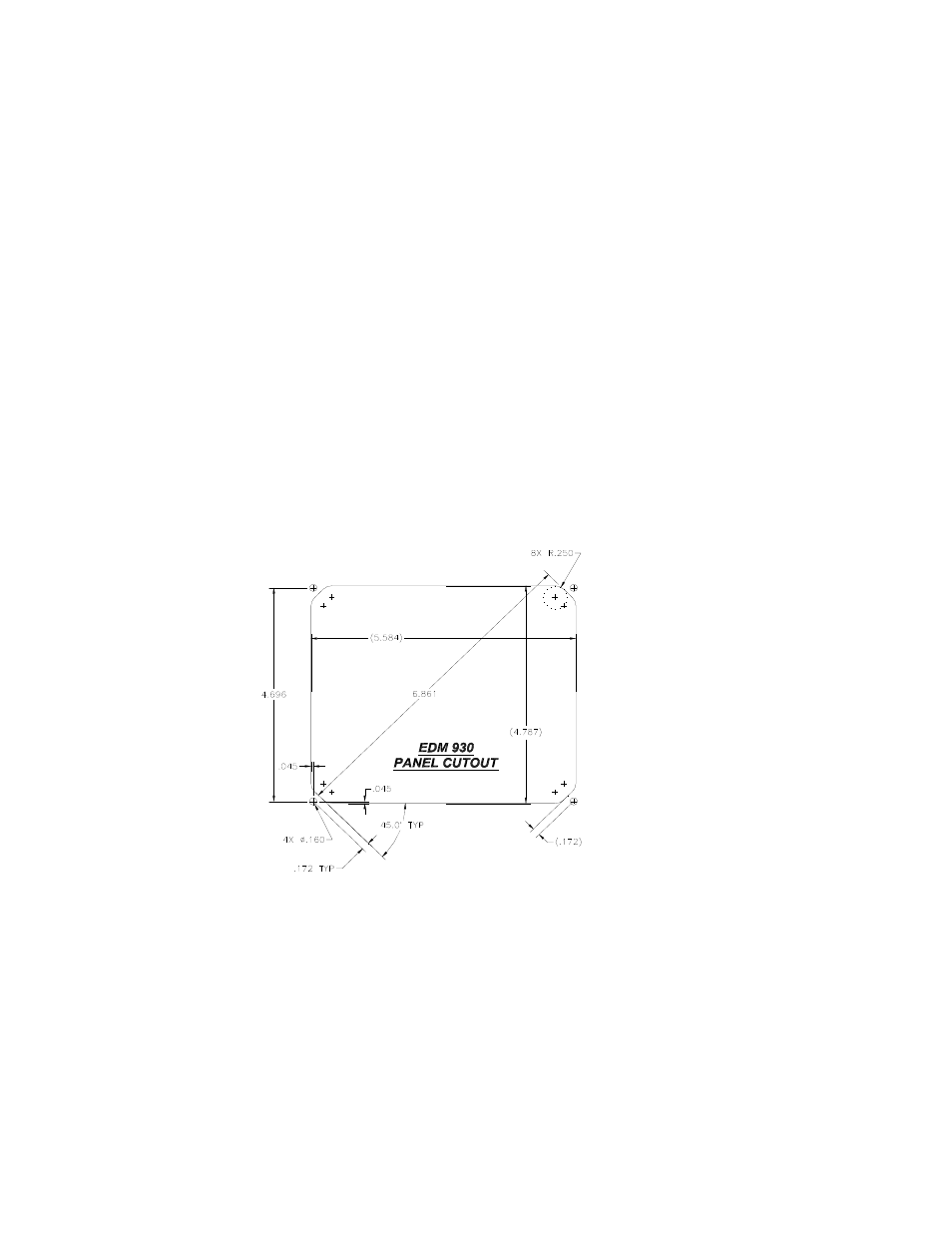
The diagram below should be used as a guide for cutting and drilling the mounting and buttonholes in the
instrument panel. The dimensions shown are for the finished cutout. Allow extra clearance for any panel finish such
as powder coat. The EDM mounts from behind the panel through this cutout. Fabricate the appropriate cut-out
using the fig below as a guide. If the panel has too many holes for a clean installation, it is recommended that a
0.10” aluminum overlay panel be constructed and installed over the original instrument panel and the EDM be
installed into this overlay panel. The Remote Alarm Display PN-790749 mounts in a 5/8 inch hole in the panel
immediately above the Attitude Gyro / D.G. / HSI +/- 0.5 inches from their centerline directly in front of the pilot.
4.1 Figure 1: