J.P. Instruments EDM 930 Primary Primary Installation Manual User Manual
Page 14
FAA Approved Installation Manual for the
Report No 908
EDM-900 and EDM-930
Page 14 of 50 Rev J
Primary Engine Data Management System Date 5-24-14
13.3 TIT for second Turbine Inlet Temperature
Use the J1 connector harness 790200 and insert the yellow wire into the connector pin 18 and the red wire into pin
19. The standard JPI TIT probe P/N M-111-T with a special clamp is placed in the exhaust stack accumulator to a
maximum depth of 1/2 inch and approximately four inches from the Turbine inlet if possible, on the waste gate side
of the turbine.
13.4
Using the Factory original TIT Probe
The factory installed TIT probe (K-calibration) is compatible with the JPI EDM-900/930 System. Connect the JPI
wire marked TIT in parallel with the factory probe noting color polarity. Replacement probes should be purchased
per part number from the aircraft manufacturer.
If you choose to use only the EDM-900/930 TIT display you may remove the factory installed TIT indicator and
leave the TIT probe installed. Connect the JPI wire marked TIT directly to the probe noting color polarity. The TIT
probe should now have only the JPI leads attached to it. No calibration of the EDM-900/930 is necessary.
14. Cylinder Head Temperature (CHT) Probe Installation
Use the J2 connector harness 700700 or 700702 labeled C1 through C4 or C6. The JPI probe is a bayonet probe
P/N 5050-T that has a captive 3/8-24 boss that is screwed into the head of each cylinder.
15. Radial Engine CHT (spark plug gasket)
Cylinder head temperatures are measured with a spark plug gasket type probe placed under the front sparkplugs.
Front spark plugs will read 15 to 20 degrees cooler than the rear plugs.
The spark plug gasket probe, P/N M-113,
replaces the standard copper spark plug gasket on one spark plug. The probe is usually placed on the plug that
receives the most direct cooling air. After many removals the probe may be annealed for re-use. Heat to 1100
o
F
and quench in water.
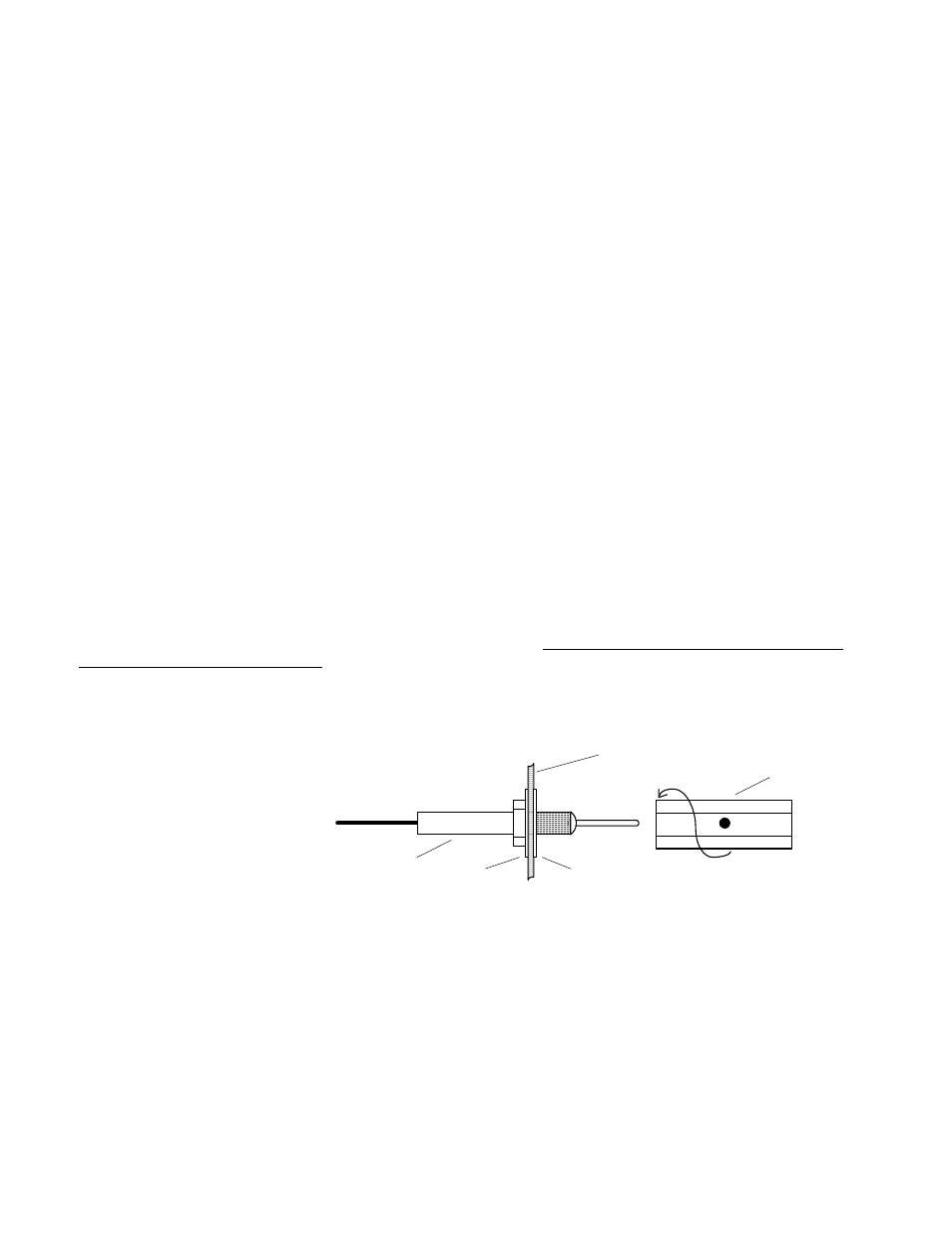
16. Outside Air Temperature (OAT) Probe Installation
Use the J1 connector harness
790200 labeled OAT. All wiring
must be type K thermocouple
wire. Do not splice ordinary
copper wire in any temperature
probe circuits.
Install the OAT probe, PN 400510
in the airframe manufacturer’s
recommended location. If this information is not available, place the OAT probe in clean airflow such as in a cabin
air scoop or below the underside of the wing away from engine heat or exhaust. In this case it is recommended that
the installation be done similar to the antenna installation instructions of AC 43.13-2b Acceptable Methods,
Techniques and Practices.
The outside aluminum shield tube is used to both hold the probe in place and shield it from radiated heat from the
sun. The OAT option is displayed as an independent digital temperature bar graph such as "75.”
16.1
Induction Air (IAT), Compressor Discharge Temperature Probe Install (optional)
Use the J1 connector harness 790200 and insert the yellow wire into the connector pin 3 and the red wire into pin
4. All wiring must be type K thermocouple wire. The Induction Air Temperature probe, (IAT), is installed just after
the inter-cooler and the Compressor Discharge Temperature (CDT) just before the inter-cooler. The probe is the
same as an EGT probe and installed similarly to an EGT probe. A large clamp is supplied to fit around the air duct
leaving the inter-cooler. Alternately a 1/8 NPT fitting is available. IAT option is displayed as an independent digital
washer
aircraft sheet metal
washer
probe
shield tube
used to secure
probe