Figure 51. filter configuration register filtcfg, Cs5376a, 7 filtcfg : 0x20 – Cirrus Logic CS5376A User Manual
Page 93
CS5376A
DS612F4
93
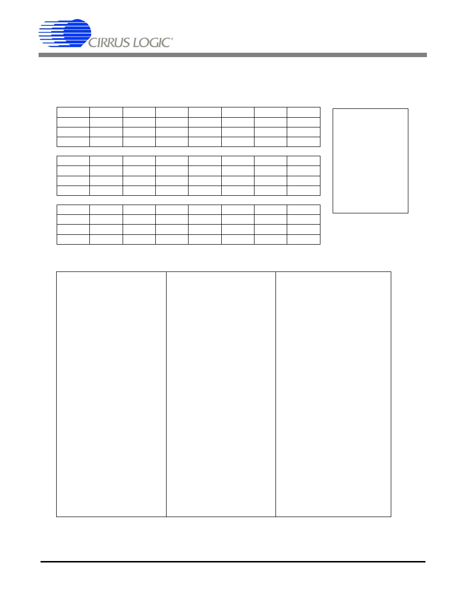
23.2.7
FILTCFG : 0x20
(MSB) 23
22
21
20
19
18
17
16
--
--
--
EXP4
EXP3
EXP2
EXP1
EXP0
R/W
R/W
R/W
R/W
R/W
R/W
R/W
R/W
0
0
0
0
0
0
0
0
15
14
13
12
11
10
9
8
--
ORCAL
USEOR
USEGR
--
FSEL2
FSEL1
FSEL0
R/W
R/W
R/W
R/W
R/W
R/W
R/W
R/W
0
0
0
0
0
0
0
0
7
6
5
4
3
2
1
(LSB) 0
DEC3
DEC2
DEC1
DEC0
--
--
CH1
CH0
R/W
R/W
R/W
R/W
R/W
R/W
R/W
R/W
0
0
0
0
0
0
0
0
DF Address: 0x20
--
Not defined;
read as 0
R
Readable
W
Writable
R/W
Readable and
Writable
Bits in bottom rows
are reset condition
Bit definitions:
23:21 --
reserved
15
--
reserved
7:4
DEC[3:0]
Decimation selection
(Output word rate)
20:16 EXP[4:0] OFFSET calibration
exponent
14
ORCAL
Run OFFSET calibration
1: Enable
0: Disable
0111: 4000 SPS
0110: 2000 SPS
0101: 1000 SPS
0100: 500 SPS
0011: 333 SPS
13
USEOR
Use OFFSET correction
1: Enable
0: Disable
0010: 250 SPS
0001: 200 SPS
0000: 125 SPS
1111: 100 SPS
1110: 50 SPS
12
USEGR
Use GAIN correction
1: Enable
0: Disable
1101: 40 SPS
1100: 25 SPS
1011: 20 SPS
1010: 10 SPS
1001: 5 SPS
1000: 1 SPS
11
--
reserved
3:2
--
reserved
10:8
FSEL[2:0] Output filter stage select
111: reserved
110: reserved
101: IIR 3rd Order
100: IIR 2nd Order
011: IIR 1st Order
010: FIR2 Output
001: FIR1 Output
000: SINC Output
1:0
CH[1:0]
Channel Enable
11: 3 Channel (1, 2, 3)
10: 2 Channel (1, 2)
01: 1 Channel (1 only)
00: 4 Channel (1, 2, 3, 4)
Figure 51. Filter Configuration Register FILTCFG