2 integrated peripheral features, 3 system level features, Figure 2. digital filtering stages – Cirrus Logic CS5376A User Manual
Page 8: Cs5376a
CS5376A
8
DS612F4
•
Digital offset correction and calibration.
-
Individual channel offset correction to re-
move measurement offsets.
-
Calibration engine for automatic calcula-
tion of offset correction factors.
1.2 Integrated Peripheral Features
•
Synchronous operation for simultaneous sam-
pling in multi-sensor systems.
-
MCLK / MSYNC output signals to syn-
chronize external components.
•
High speed serial data output port (SD port).
-
Asynchronous operation to 4 MHz for di-
rect connection to system telemetry.
-
Internal 8-deep data FIFO for flexible out-
put timing.
•
Digital test bit stream signal generator suitable
for CS4373A
∆Σ test DAC.
-
Sine wave output mode for testing total har-
monic distortion.
-
Programmable waveform data for custom
test signal generation.
•
Time break controller to record system timing
information.
-
Dedicated TB status bit in the output data
stream.
-
Programmable output delay to match sys-
tem group delay.
•
Additional hardware peripherals simplify sys-
tem design.
-
12 General Purpose I/O (GPIO) pins for lo-
cal hardware control.
-
Secondary SPI 2 serial port to control local
serial peripherals.
-
JTAG port for boundary scan (IEEE 1149.1
compliant).
1.3 System Level Features
•
Flexible configuration options.
-
Configuration 'on-the-fly' via microcontrol-
ler or system telemetry.
-
Fixed configuration via stand-alone boot
EEPROM.
•
Low power consumption.
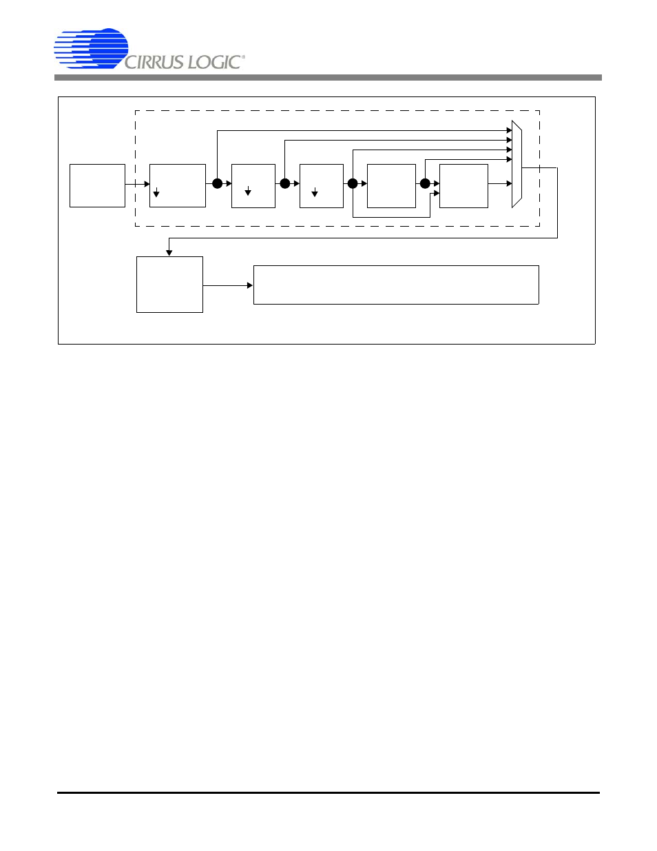
Figure 2. Digital Filtering Stages
Sinc Filter
2 - 64000
FIR1
4
FIR2
2
IIR1
IIR2
1
st
Order
2
nd
Order
Output to High Speed Serial Data Port
DC Offset
Corrections
Output Word Rate from 4000 SPS ~ 1 SPS
Gain &
Modulator
512 kHz
Input