Synchronization, 1 pin description, 2 msync generation – Cirrus Logic CS5376A User Manual
Page 25: 3 digital filter synchronization, 4 modulator synchronization, 5 test bit stream synchronization, Figure 13. synchronization block diagram, Cs5376a
CS5376A
DS612F4
25
7. SYNCHRONIZATION
The CS5376A has a dedicated SYNC input that
aligns the internal digital filter phase and generates
an external signal for synchronizing modulator an-
alog sampling. By providing simultaneous rising
edges to the SYNC pins of multiple CS5376A de-
vices, synchronous sampling across a network can
be guaranteed.
7.1 Pin Description
SYNC - Pin 59
Synchronization input, rising edge triggered.
7.2 MSYNC Generation
The SYNC signal rising edge is used to generate a
retimed synchronization signal, MSYNC. The
MSYNC signal reinitializes internal digital filter
phase and is driven onto the MSYNC output pin to
phase align modulator analog sampling.
The MSEN bit in the digital filter CONFIG register
(0x00) enables MSYNC generation. See “Modula-
tor Interface” on page 39 for more information
about MSYNC.
7.3 Digital Filter Synchronization
The internal MSYNC signal resets the digital filter
state machine to establish a known digital filter
phase. Filter convolutions restart, and the next out-
put word is available one full sample period later.
Repetitive synchronization is supported when
SYNC events occur at exactly the selected output
word rate. In this case, re-synchronization occurs at
the start of a convolution cycle when the digital fil-
ter state machine is already reset.
7.4 Modulator Synchronization
The external MSYNC signal phase aligns modula-
tor analog sampling when connected to the
CS5371A/72A MSYNC input. This ensures syn-
chronous analog sampling relative to MCLK.
Repetitive synchronization of the modulators is
supported when SYNC events occur at exactly the
selected output word rate. In this case, synchroni-
zation will occur at the start of analog sampling.
7.5 Test Bit Stream Synchronization
When the test bit stream generator is enabled, an
MSYNC signal can reset the internal data pointer.
This restarts the test bit stream from the first data
point to establish a known output signal phase.
The TSYNC bit in the digital filter TBSCFG regis-
ter (0x2A) enables synchronization of the test bit
stream by MSYNC. When TSYNC is disabled, the
test bit stream phase is not affected by MSYNC.
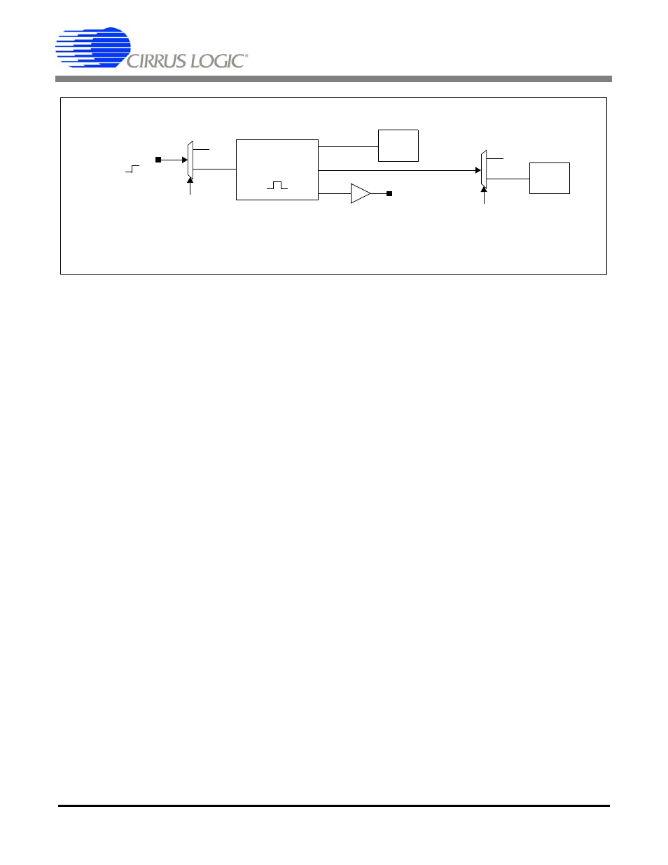
Figure 13. Synchronization Block Diagram
SYNC
MSYNC
Digital
Filter
Generator
MSYNC
0
1
MSEN
0
1
TSYNC
Test Bit
Stream
Output