Figure 26. fir filter stages, Table 12. fir filter characteristics, Cs5376a – Cirrus Logic CS5376A User Manual
Page 49
CS5376A
DS612F4
49
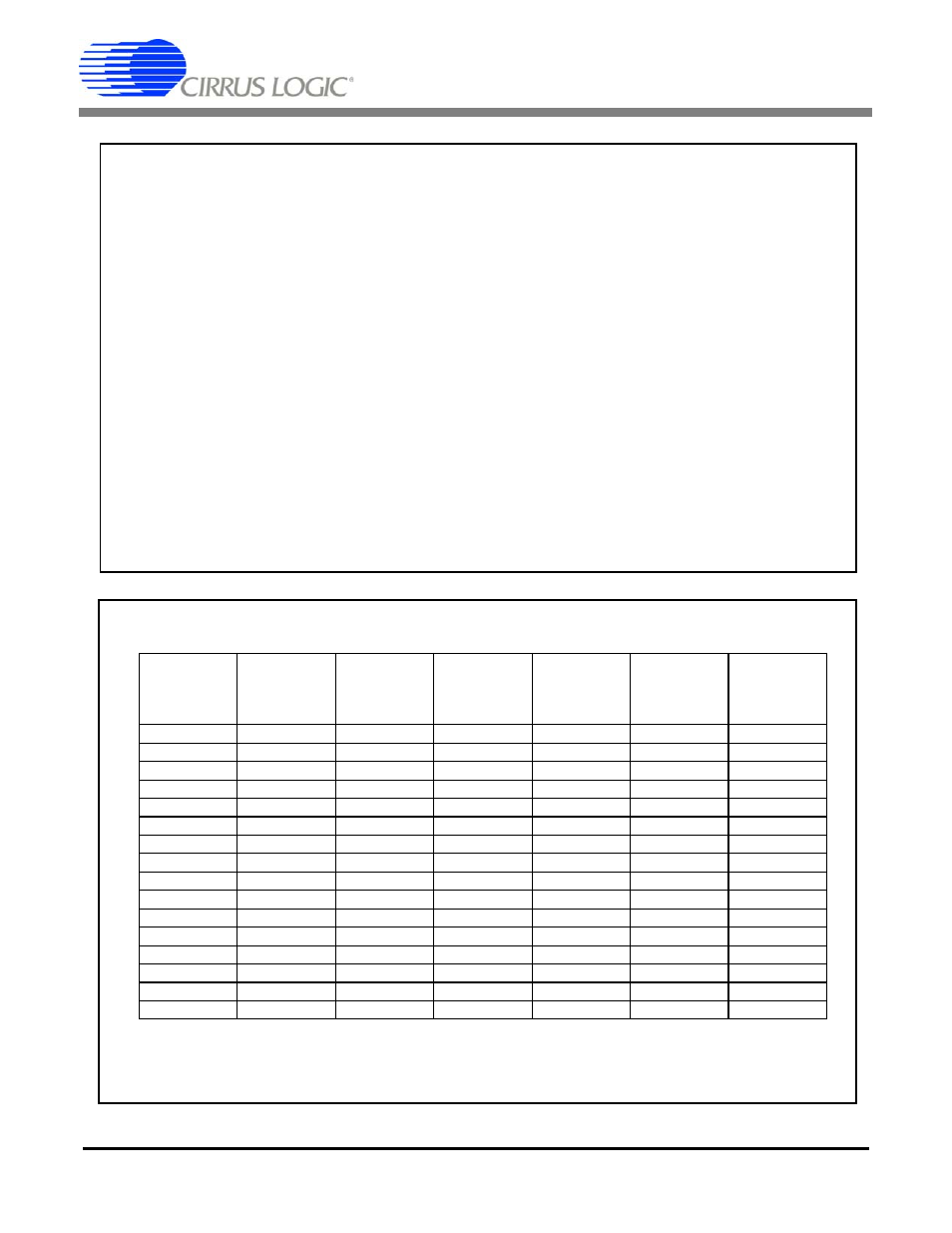
FIR1 – Single stage, fixed decimate by 4
Coefficient set 0: linear phase decimate by 4, 48 coefficients
Coefficient set 1: minimum phase decimate by 4, 48 coefficients
SINC droop compensation filter
FIR2 – Single stage, fixed decimate by 2
Coefficient set 0: linear phase decimate by 2, 126 coefficients
Coefficient set 1: minimum phase decimate by 2, 126 coefficients
Brick wall low-pass filter, flat to 40% f
s
Combined SINC + FIR digital filter specifications
Passband ripple less than +/- 0.01 dB below 40% f
s
Transition band -3 dB frequency at 42.89% f
s
Stopband attenuation greater than 130 dB above 50% f
s
Figure 26. FIR Filter Stages
SINC + FIR filters
FIR2
Output
Word
Rate
SINC
Deci-
mation
FIR1
Deci-
mation
FIR2
Deci-
mation
Total
Deci-
mation
Passband
Ripple
(
± dB)
Stopband
Atten-
uation
(dB)
4000 16
4
2 128
0.0042
130.38
2000 32
4
2 256
0.0045
130.38
1000 64
4
2 512
0.0040
130.42
500 128 4
2 1024
0.0041
130.42
333 192 4
2 1536
0.0080
130.45
250 256 4
2 2048
0.0064
130.43
200 320 4
2 2560
0.0041
130.43
125 512 4
2 4096
0.0046
130.42
100 640 4
2 5120
0.0040
130.43
50 1280 4
2 10240
0.0040
130.43
40 1600 4
2 12800
0.0036
130.43
25 2560 4
2 20480
0.0040
132.98
20 3200 4
2 25600
0.0036
130.43
10 6400 4
2 51200
0.0036
130.43
5 12800 4
2 102400
0.0036
130.43
1 64000 4
2 512000
0.0029
134.31
Table 12. FIR Filter Characteristics