4 eeprom configuration commands, Eeprom configuration commands, Figure 16. 8 kbyte eeprom memory organization – Cirrus Logic CS5376A User Manual
Page 28: Table 4. maximum eeprom configuration, Cs5376a
CS5376A
28
DS612F4
5 KByte (40 Kbit), which includes command over-
head:
Supported serial configuration EEPROMs are
SPI mode 0 (0,0) compatible, 16-bit addresses, 8-
bit data, larger than 5 KByte (40 KBit). ATMEL
AT25640, AT25128, or similar serial EEPROMs
are recommended.
8.4 EEPROM Configuration
Commands
A summary of available EEPROM commands is
shown in Table 5.
Write DF Register - 0x01
This EEPROM command writes a data value to the
specified digital filter register. Digital filter regis-
ters control hardware peripherals and filtering
functions. See “Digital Filter Registers” on page 86
for the bit definitions of the digital filter registers.
Sample Command:
Write digital filter register 0x00 with data value
0x070431. Then write 0x20 with data 0x000240.
01 00 00 00 07 04 31
01 00 00 20 00 02 40
Write FIR Coefficients - 0x02
This EEPROM command writes custom coeffi-
cients for the FIR1 and FIR2 filters. The first two
data words set the number of FIR1 and FIR2 coef-
ficients to be written. The remaining data words are
the concatenated FIR1 and FIR2 coefficients.
A maximum of 255 coefficients can be written for
each FIR filter, though the available digital filter
computation cycles will limit their practical size.
See “FIR Filter” on page 47 for more information
about FIR filter coefficients.
Sample Command:
Write FIR1 coefficients 0x00022E, 0x000771 then
FIR2 coefficients 0xFFFFB9, 0xFFFE8D.
02 00 00 02 00 00 02
00 02 2E 00 07 71 FF FF B9 FF FE 8D
Write IIR Coefficients - 0x03
This EEPROM command writes custom coeffi-
cients for the two stage IIR filter. The IIR architec-
ture and number of coefficients is fixed, so eight
data words containing coefficient values always
immediately follow the command byte. The IIR co-
efficient write order is: a11, b10, b11, a21, a22,
b20, b21, and b22. See “IIR Filter” on page 55 for
more information about IIR filter coefficients.
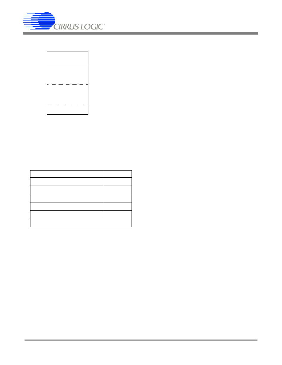
Figure 16. 8 Kbyte EEPROM Memory Organization
0000h
1FFFh
EEPROM
Manufacturing
Information
EEPROM
Command and
Data Values
Mfg Header
8-bit Command
0010h
N x 24-bit Data
8-bit Command
N x 24-bit Data
. . .
Table 4. Maximum EEPROM Configuration
Memory Requirement
Bytes
Digital Filter Registers (22)
154
FIR Coefficients (255+255)
1537
IIR Coefficients (3+5)
25
Test Bit Stream Data (1024)
3076
‘Filter Start’ Command
1
Total Bytes
4793