Configuration by microcontroller, 1 pin descriptions, 2 microcontroller hardware interface – Cirrus Logic CS5376A User Manual
Page 32: 3 microcontroller serial transactions, Cs5376a
CS5376A
32
DS612F4
9. CONFIGURATION BY MICROCONTROLLER
After reset, the CS5376A reads the state of the
BOOT pin to determine a source for configuration
commands. If BOOT is low, the CS5376A receives
configuration commands from a microcontroller.
9.1 Pin Descriptions
Pins required for microcontroller boot are listed
here, other SPI 1 pins are inactive.
SSI - Pin 49
Slave select input pin, active low. Serial chip select
input from a microcontroller.
SCK1 - Pin 48
Serial clock input pin. Serial clock input from mi-
crocontroller, maximum 4.096 MHz.
MOSI - Pin 51
Serial data input pin. Valid on rising edge of SCK1,
transition on falling edge.
MISO - Pin 50
Serial data output pin. Valid on rising edge of
SCK1, transition on falling edge. Open drain out-
put requiring a 10 k
Ω pull-up resistor.
SINT - Pin 52
Serial interrupt output pin, active low. 1 uS active
low pulse output when ready for next serial trans-
action.
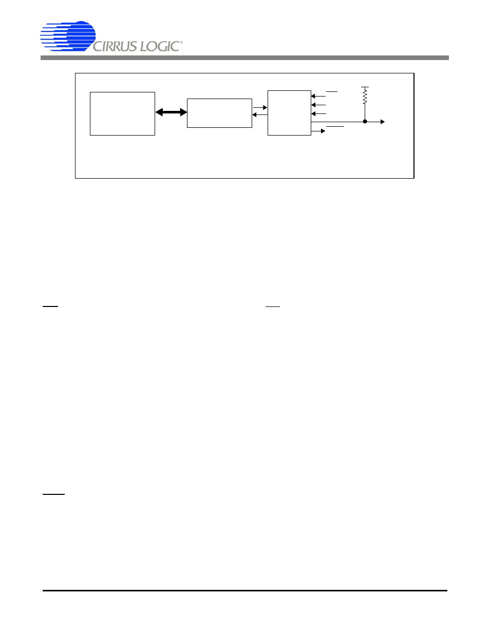
9.2 Microcontroller Hardware Interface
When booting from a microcontroller the
CS5376A SPI 1 port receives configuration com-
mands and configuration data through serial trans-
actions, as shown in Figure 18. 8-bit SPI opcodes
and 8-bit addresses are combined to read and write
24-bit configuration commands and data.
Microcontroller serial transactions require toggling
the SSI pin as the CS5376A chip select and writing
a serial clock to the SCK1 input. Serial data is input
to the CS5376A on the MOSI pin, and output from
the CS5376A on the MISO pin.
9.3 Microcontroller Serial Transactions
Microcontroller configuration commands are writ-
ten to the digital filter through the SPI 1 registers.
A 24-bit command and two 24-bit data words can
be written to the SPI 1 registers in any single serial
transaction. Some commands require additional
data words through additional serial transactions to
complete.
9.3.1 SPI opcodes
A microcontroller communicates with the
CS5376A SPI 1 port using standard 8-bit SPI op-
codes and an 8-bit SPI address. The standard SPI
‘Read’ and ‘Write’ opcodes are listed in Figure 18.
SCK1
MISO
MOSI
Pin Logic
SPI 1
Figure 17. Serial Peripheral Interface 1 (SPI 1) Block Diagram
SINT
Command
SSI
Registers
Digital Filter
Interpreter
SPI 1